


23 September 2023
|
 Here's a job that you can do for next to nothing
: credit: © Alisdair Cusick
Here's a job that you can do for next to nothing
: credit: © Alisdair Cusick
Alisdair Cusick shows how to repair an original vacuum advance unit for just a few pounds
Need to know
Time: 3 hours
Difficulty: 1 out of 5
Models: All petrol model Land Rovers using Lucas vacuum advance.
Tools needed: Screwdrivers, mallet/hammer, drift, old (sharp) screwdriver, grips, wood tools for form-making, drill, thread tap, instant glue, spanner set, pliers.
Parts used: Nitrile rubber sheet £3.13, eBay and most rubber and gasket suppliers.
Work safely:
• Use the right tool for the right job.
• Never take risks with electrical wiring.
• If in any doubt, employ an expert to do the job.
• Take extra care using hammers in close work.
A fully functioning ignition system is vital for a well-performing petrol Land Rover. It is often said most suspected carburettor issues are actually caused by the ignition system, and it is partly true. Ignition components are required to work in harmony for the spark to happen at the correct time and in the correct place, so this needs to be confirmed before you even think of issues around delicately balancing the mix of fuel and air in the carb.
One often overlooked ignition component is the vacuum advance unit, which is the flying saucer-shaped attachment outside the distributor. Its job is to advance the ignition timing under part or steady throttle, to aid better combustion and improve fuel economy. It does this by reacting to vacuum in the intake manifold, through a port typically below the carburettor butterfly valve.
How it works
Under a wide-open throttle condition, lots of fuel is squirted in and greedily combusted but, under steady throttle, or having backed off the throttle, a different situation occurs. The engine cylinders aren’t being fed lots of fuel – in fact, the carb butterfly is restricting the amount of air (and therefore fuel) the inlet can get. The movement of the pistons creates suction at the inlet manifold on their intake stroke, between carb and inlet valves. In this state, combustion can take longer to occur, meaning the ignition timing needs advancing, so as to place the spark at an earlier point of the crank rotation. This is the vacuum advance’s job. The vacuum of the inlet manifold is harnessed to move a diaphragm inside the vacuum advance, which operates a rod connected to the distributor baseplate. As manifold vacuum increases, the diaphragm moves with the suction, thereby advancing the timing as needed inside the distributor.
The distributor also has a mechanical advance system which advances the timing for the same reason – to allow time for the fuel to ignite as engine speed increases – but the mechanical system uses centrifugal counterweights inside the distributor and operates via set engine speeds. Vacuum advance works independently of mechanical advance, and operates at any speed, dictated by manifold pressure. Combined together, our distributor has a mapped advance curve specific to our engine, plotting a level of advance relating to both engine speed and manifold vacuum to constantly optimise engine performance.
Engine specific
Vacuum advance units are specified and rated for each vehicle and engine, something like 7-18-12. This designation means the advance would begin to increase after a vacuum of 7 inches of mercury (ins Hg) is reached, and would continue increasing until 18 ins Hg is reached, at which point the maximum advance of 12 degrees would be applied to the timing.
How to check
Any issue with the vacuum’s diaphragm means the timing won’t be advanced when needed. Low-throttle performance will drop off, the engine may feel sluggish at low revs, plugs may foul a little under a trailing throttle, and fuel consumption will increase. This is because the timing is effectively retarded for conditions of high manifold vacuum demand.
The easiest way to check performance is to remove the vacuum pipe on the advance unit, and apply suction. The human lung may not create enough suction, so mechanical suction from a brake bleeder, or syringe may be needed. Simply apply suction and watch the distributor baseplate, which you should see rotate a little.
If it does rotate, hold it under suction: the baseplate should hold position. If it rotates back to rest, or indeed doesn’t move at all, then you have a vacuum leak, meaning your diaphragm has failed.

Big fat fail: Apply suction to the advance unit. The vacuum should move the distributor baseplate, and hold position. Mine barely made the plate twitch, and it instantly returned to rest.
The cure
Remanufactured units, to the correct advance curve as your original unit, may be available, but that isn’t the only option. The original units can usually be repaired, right back to those from 1948. What’s more, the repair costs only a few pounds and takes around three hours.
Here, I show you how to test and repair the vacuum advance on my 1957 2.0-litre Series I, but the principle is the same for any Lucas vacuum advance unit. When was the last time you performed a repair using a wooden former? This is one job where the fix blends modern materials with old school skills.
Accessing the diaphragm

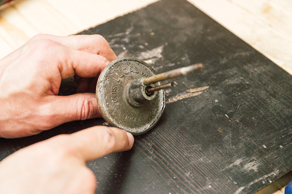
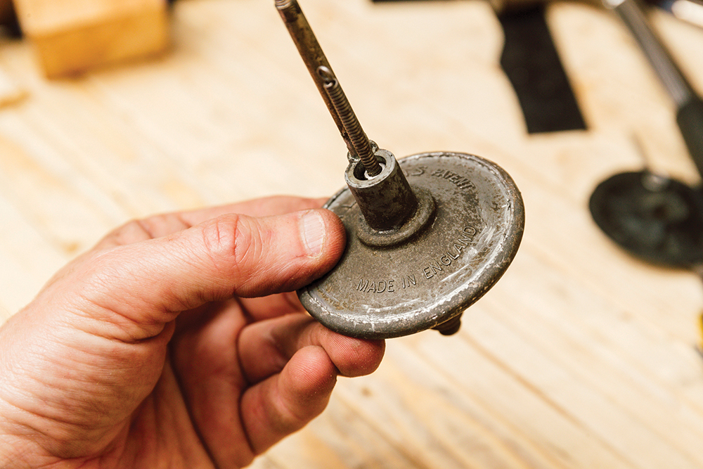
Remove the unit: Having disconnected the vacuum line in, I release the advance baseplate connecting spring, here. Off comes the adjuster nut and the advance unit simply withdraws from the distributor.
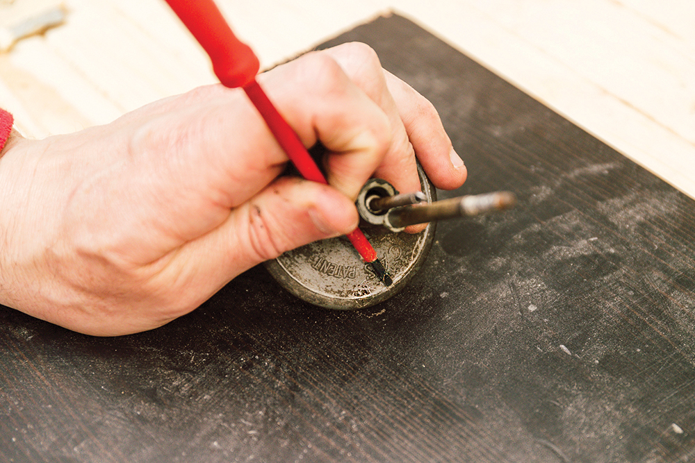
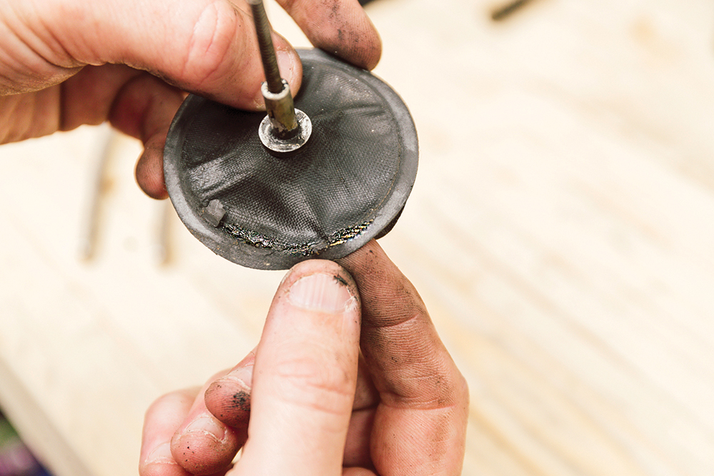
The task: Here, I’m separating the diaphragm case. Using a sharp (old) screwdriver, gently tap it into the folded edge joint to separate it, working all the way around.
Work it out: Strive to keep the lip even as it opens out. Rush and the case metal will irreparably split. Here, after 15 minutes’ work, the gap is larger.

Bigger tools: A larger screwdriver can be used eventually, to just lever out the edge. Again, going slowly, work around the outer lip to open it more and more.
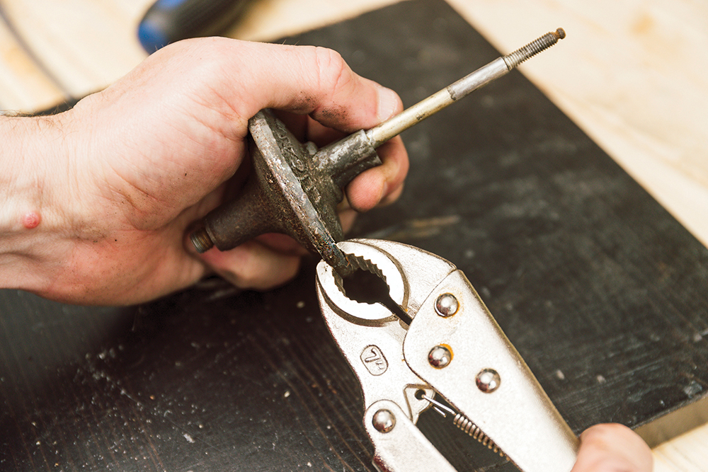
Nearly there: When it gets to almost 90 degrees, some grips or pliers can be used to lever out the edge, using the tool carefully so not to cause damage.
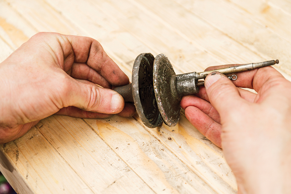
Off it comes: The outer lip opens enough to release the two halves. They are under gentle spring pressure. As they separate, don’t lose that spring and its locating rod.

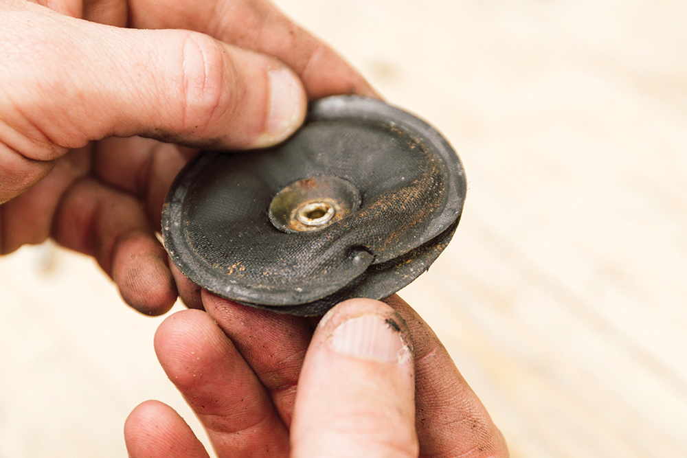
Vital part: The diaphragm can be removed from the case with the distributor operating spring. This one last saw daylight in 1957, and doesn’t look too bad after 65 years.
Inspection: Inspect the diaphragm, which is two pieces of thin material bonded together. The back face shows a clear split. No wonder it wouldn’t hold any vacuum.
Not only, but also: The other side shows a possible manufacturing defect, where the material is pulled away from the edge. It may have been like this all the time, who knows?
Repairing the unit
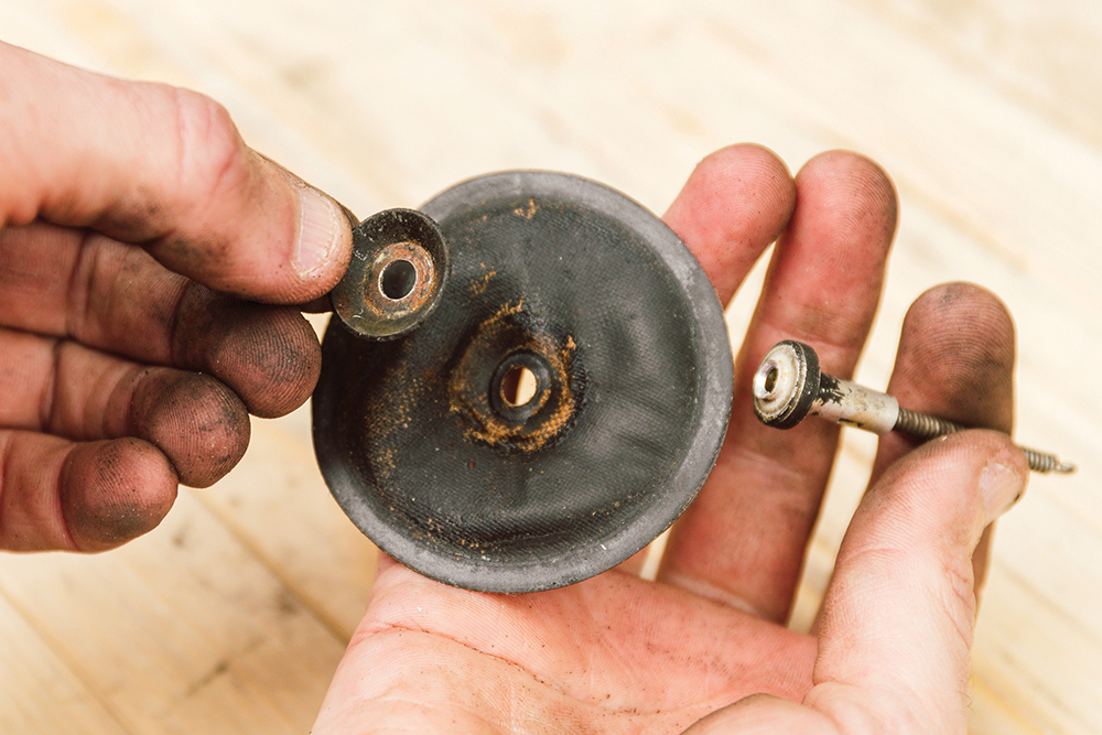
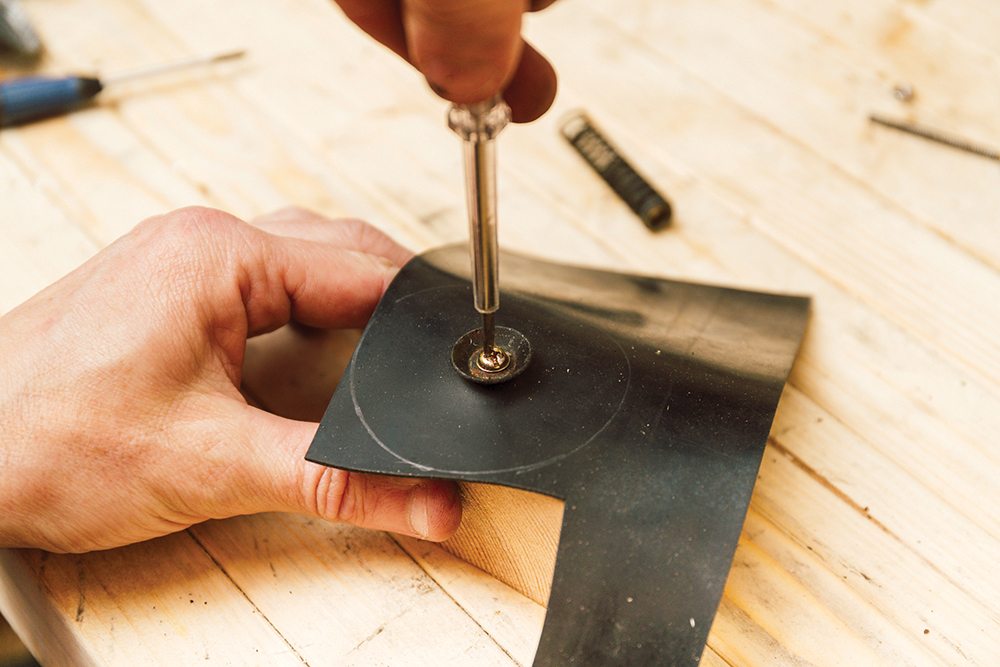
Repair begins: A small rivet holds the diaphragm to its operating rod. Carefully drill the top off, releasing the material. Only the rivet head is removed, no rod material.
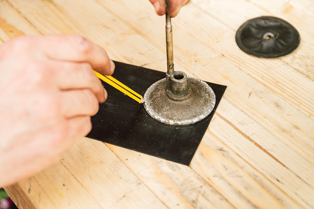
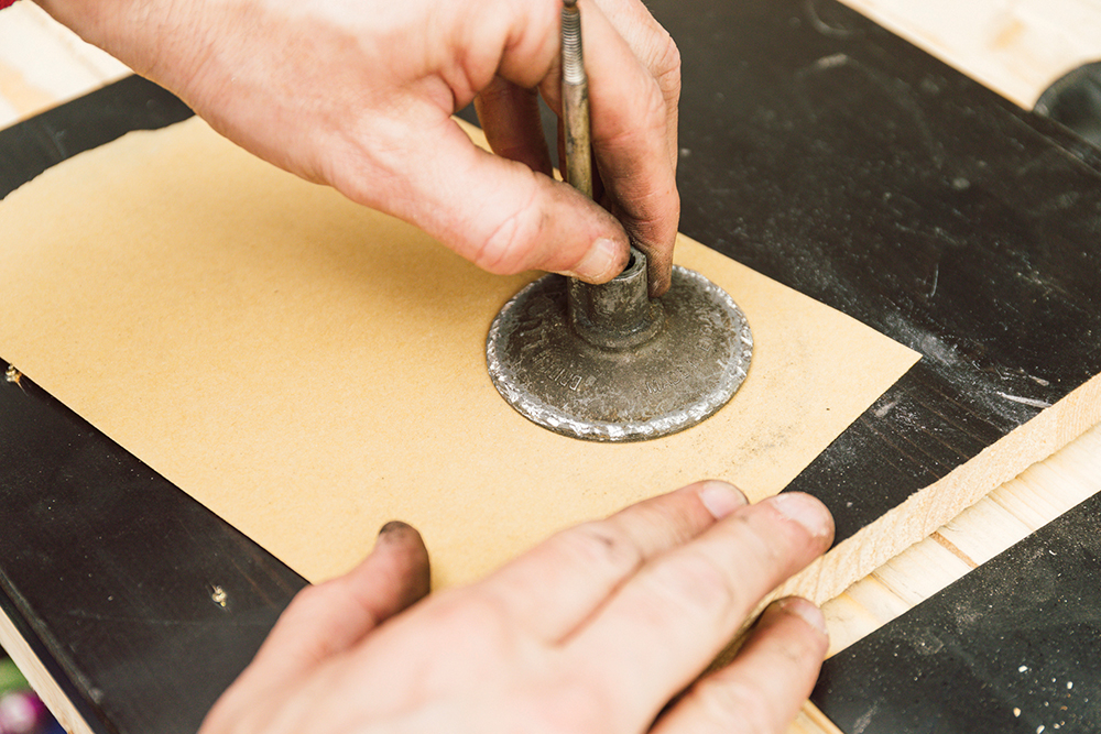
Modern material: A piece of 1mm nitrile rubber sheet is used for a new diaphragm. The diaphragm side of the vacuum unit is used to mark out the material required.
Extra step: The mating face needs cleaning, but I go a step further and flatten it a touch on some fine sandpaper on a flat surface – not strictly necessary, though.
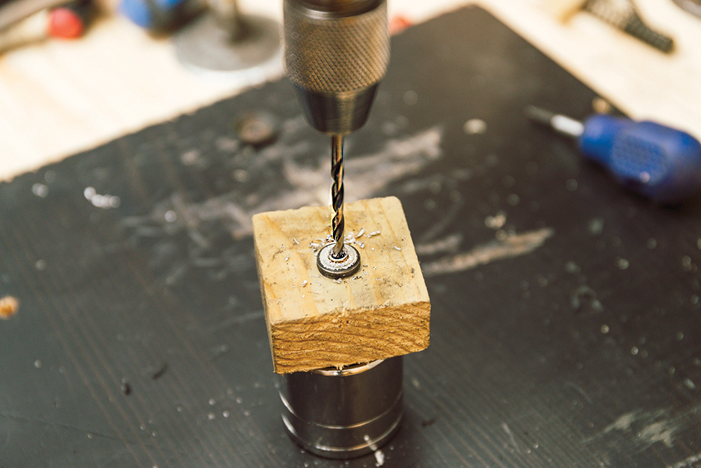
Hold it tight: The rod is held firm and square through a wood block as I use a pillar drill to make a 3.5mm hole for a screw to fix the new diaphragm.
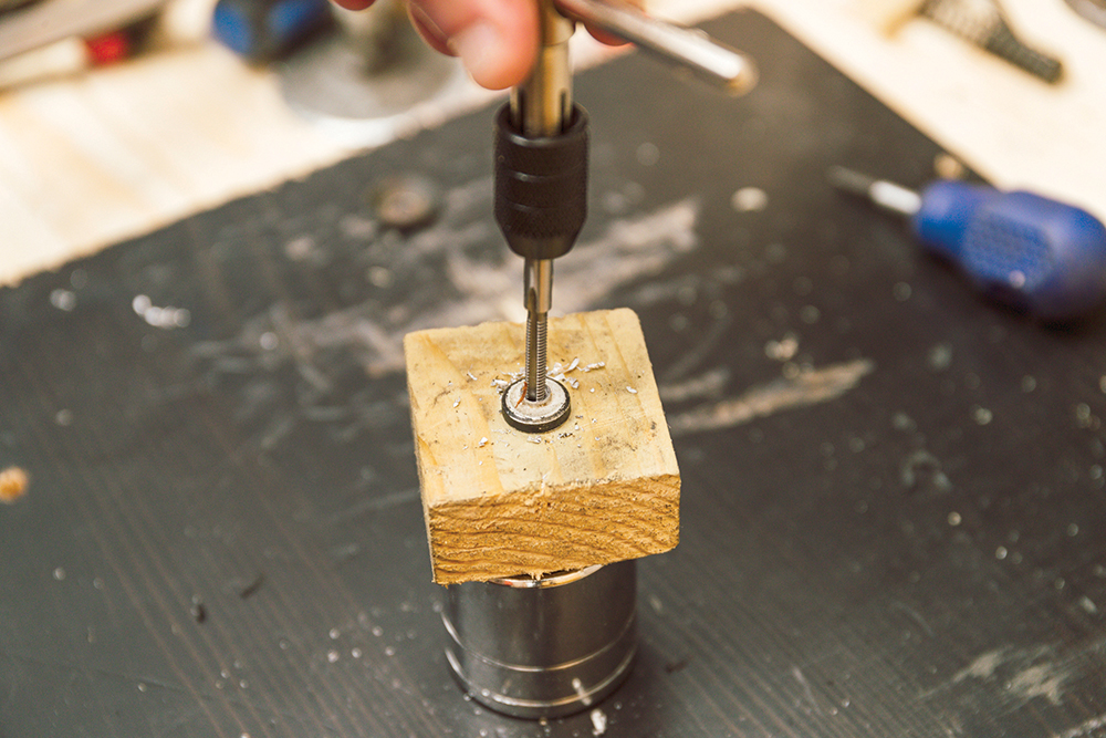
Tap a thread: Use a tap to cut an M4 thread, going just deep enough. Light oil helps preserve the tool. Purists might prefer BA thread, or BSF, for authenticity.
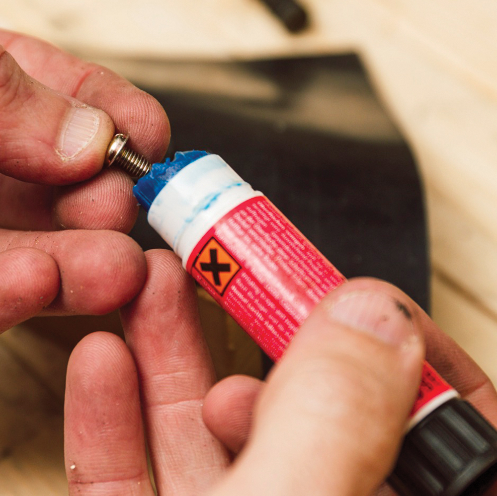
Fixing help: I’ve shortened an M4 screw, ensuring to re-form the cut threads afterwards. A dab of thread lock gives a little extra help to prevent it undoing in use.
Assembly: Supporting the rod, the diaphragm and washer are fixed in position. I’m ready now to fix the new part to the advance housing. For that, I use glue.
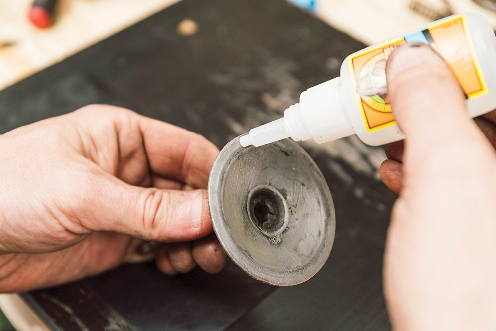
Stick the edge: The best glue for rubber is cyanoacrylate, or super glue. The folded case edge should hold the diaphragm, but glue on the edge bonds it now.
Sealed: The glue should cure almost instantly, but I weigh the component down for an hour. The excess material is trimmed – leaving a little extra helps make a seal.

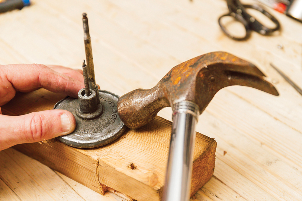
Wooden form: Shape a wooden former to support the lower case right out to the edges. Wood supports without causing any witness marks on the advance case from hammering.
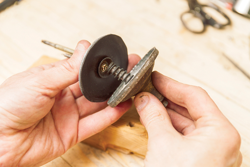
Assembly time: Refit the diaphragm to the case, making sure to locate the spring rod’s cup over the M4 screw head. Then the two sides are held together tightly.

Begin the refit: With the unit in my custom dolly, I begin hammering the lip. Start horizontally, tapping very gently, and working repeatedly around the edge. Lots of tiny taps.
Slow progress: As the lip goes tighter, my work angle raises, folding the edge over. Work from the outside, carefully not overworking the metal, or else it will split.

Finishing: Eventually I swap to a larger, flat dolly, flattening the edge downwards. If I’ve done it right, this should sit tightly and make an airtight seal in itself.
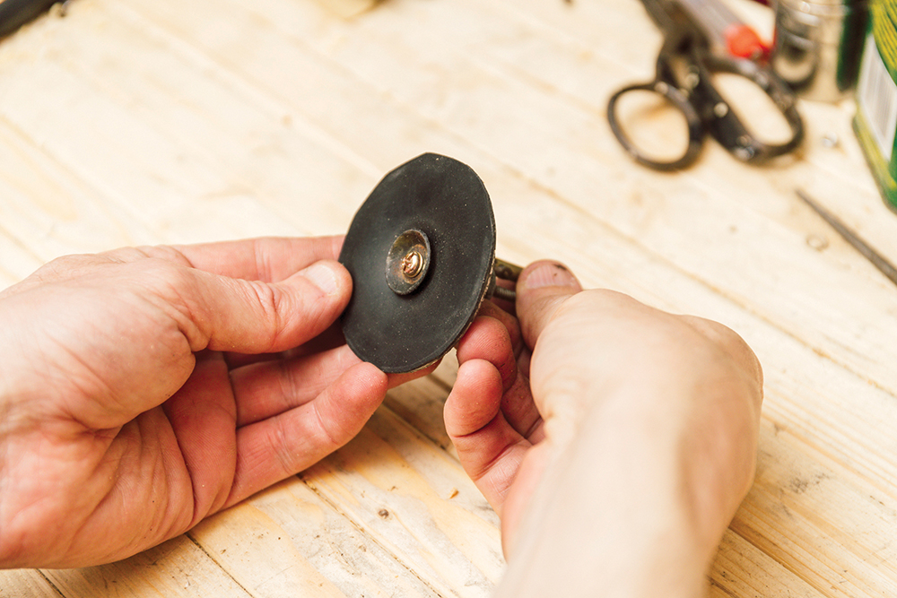
Good as new: The end result is a folded over edge. My slow work means I’ve avoided fracturing the metal and made only minimal surface marks on the component.

Fit to the car: The unit goes back on the car and I adjust the advance to the middle of its range. Applying suction sees the baseplate move, and hold that position beautifully.
A result
A road test with a now functioning vacuum advance should reveal a little more willingness from lower revs, and in mid-range pickup from a cruise as the baseplate advances the ignition timing from the manifold vacuum: the advanced timing permits more time for the fuel to burn so, basically, the piston gets the biggest bang, in the right place. Sure enough, my road test exactly confirms that this low-down torque and willingness has returned. A longer run should also give a little improvement to the fuel economy.
Like to have your own Land Rover library?
Try our Budget Digital Subscription. You'll get access to over 7 years of Land Rover Monthly – that’s more than 100 issues plus the latest digital issue. All issues are fully searchable so you can easily find what you are looking for and what’s more it’s less than 10p a day to subscribe. Click here to find out more details and start enjoying all the benefits now.