


16 March 2024
|
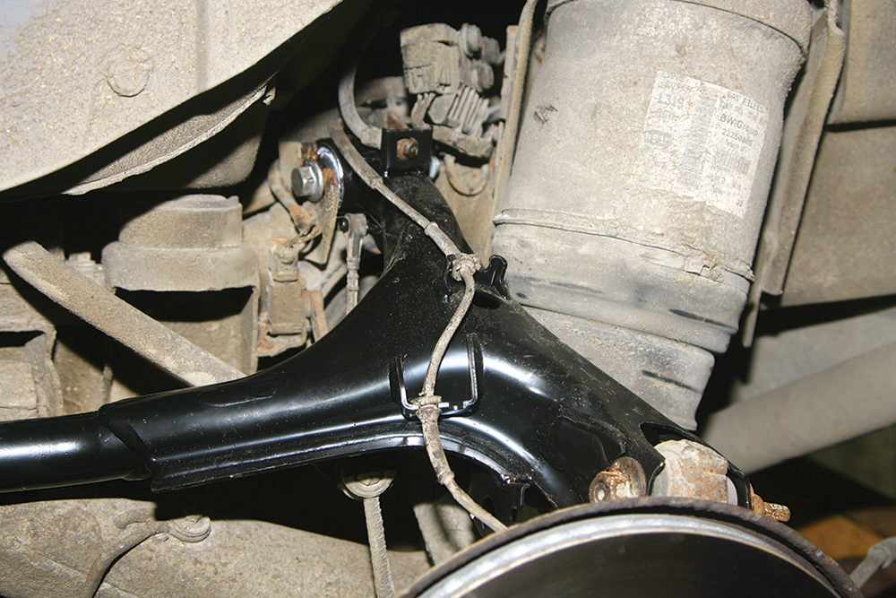
 The upper control arm is located to the chassis by two rear bushes (the bush to the right has failed), and to the hub knuckle by a ball joint (foreground)
: credit: © Dave Barker
The upper control arm is located to the chassis by two rear bushes (the bush to the right has failed), and to the hub knuckle by a ball joint (foreground)
: credit: © Dave Barker
Coping with weight and strong forces means independent suspension bushes wear fast. Dave Barker explains a cost-effective repair
Need to know
Time taken: 1½ hours
Tools needed: General workshop tools including 18, 19 and 20mm spanners and sockets, socket extension bar, pry bar and torque wrench, jack and axle stands or preferably a vehicle lift.
Difficulty: 2 out of 5 (or possibly 3 out of 5 if all the bush bolts are seized).
Models: Discovery 3 and 4, Range Rover Sport 1.
Parts used: Parts apply to our 2010 Discovery 4, confirm for your vehicle.
• LR051623 (this is the left-hand) rear upper control arm, from £72 to over £380 for a genuine part.
• RYH501060 flanged nut, from £4 to £6.50 for a genuine part.
• FC116216 bolt M16x105mm, from £4 to £11 for a genuine part.
Work Safely
• Before working underneath a vehicle, ensure jacks, axle stands and vehicle lifts are correctly rated and in good order.
• Ensure the vehicle is secure when raised and cannot be dislodged when pulling on spanners.
• Wear gloves or barrier cream to protect skin from fluids, oils and sharp edges of components.
• A dust filter mask and eye protection are advised.
• When using the angle grinder, wear thick gloves and eye protection and be aware of fire hazards from the sparks and torque twist from the grinder.
• Confirm and use the torque settings for the fixings on your particular vehicle.
Thanks to: Maddison 4x4, Water House Farm, Station Road, Topcliffe near Thirsk, YO7 3SG.
Maddison4x4.com. 01845 587407.
During this Discovery 4’s pre-MoT inspection the rearward bush in a rear upper control arm showed signs of excessive play. Any worn suspension bush can impact vehicle handing, causing vibration or shimmying and adversely affecting steering. It can also increase stress and wear and tear on other suspension parts and tyres, and even component failure if extreme wear allows metal to metal contact. So, not withstanding the obvious MoT failure, a worn bush needs to be replaced as soon as practical.
This 2010 Discovery was still on its original factory fitted rear control arms, which is surprising given that worn bushes seem to be a common problem on Discovery 3 and 4 models and Range Rover Sport 1. There is the option to replace just the worn bush or bushes or to replace the complete suspension arm. Replacing the complete arm usually takes the same time as replacing a single bush, and both options involve removing the arm from the vehicle. Usually at least one of the control arm bush bolts will be seized into the bush and has to be cut off. Cost can also be a factor because the cost of two new bushes alone can be around £100 depending on the make and where you buy them from, whereas a new control arm can be found from £75 upwards.
Replacing the upper rear control arm is not a difficult job in itself, the only problem is if any of the bolts are seized into their bushes and require being cut off. On this vehicle, only the worn bush had its bolt seized inside, so that single bolt needed to be cut up using an angle grinder.
It’s also easier, and advisable, to replace the short section of metal brake pipe that runs along the control arm from the rear brake hose to the brake caliper hose. It’s often corroded, especially at the unions. It’s easier to cut the pipe and fit a new one, and they are available as a made up Land Rover part for around £18; alternatively most garages will make one up for you.
Here we show the process of changing the left-hand side rear upper arm; the right-hand side is a similar job.
Removing the upper control arm

Cam bolt: With the wheel removed, the ball joint’s cam bolt flange is referenced to the arm using a centre punch. This aids alignment when refitted to the new arm.

Ball joint: The self-locking nut and eccentric washer are now removed from the cam bolt and the bolt is tapped out, thus releasing the ball joint from the arm.

Unclip and release: The wheel speed sensor wiring harness is carefully unclipped from the two cable holders (arrowed) and released from the top of the rear control arm.
Brake circuit
It’s necessary to disconnect the brake line, so in order to minimise fluid loss a purpose-made brake hose clamp is fitted to the upper hose before disconnecting the pipes. This also prevents air entering the system, making bleeding the brake after reassembly more straightforward.
Cut off: Here it was quicker to cut the old brake pipe out and unscrew the unions from the hoses later after wire brushing and leaving to soak in penetrating fluid.

Release the hoses: Using a pry bar, both top and bottom clips holding the brake hose fitting to the control arm are released, then pulled out from the bracket (below).


Height sensor: We’re almost ready to start removing the upper arm, but first the ride height sensor link is disconnected from the steel lug under the upper arm.

Forward bush: The bolt securing the control arm forward bush to its chassis mounting bracket is undone and the bolt and the caged nut removed and retained.

Seized bolt: The bolt through the rearward worn bush securing the upper arm into position is seized solid inside the metal sleeve of the bush and has to be cut off.

Cut off: Using an angle grinder with a thin cutting disc, the bolt is cut carefully between the arm and the bracket. The nut and washer can then be levered out.

Pry out: With the bolt now cut through, the rearward bush and upper arm is then forced upwards and freed from its chassis mounting bracket.

Remove the arm: With the chassis bushes and ball joint now free, the control arm can be lifted from the vehicle for either rebushing or, as in this case, complete replacement.

Inspection: With the upper control arm now on the bench, the worn bush is removed from the suspension arm and the full extent of the wear can be clearly seen.
Re-assembly with the new arm

New arm: The replacement upper control arm is supplied complete with the two rear chassis bushes pre-fitted. The original knuckle ball joint can be retained, or renewed if worn.

New bolts: Given the rearmost chassis bush bolt had to be cut out due to seizure, we renew this bolt and its caged nut. Other bolts are rust-free after cleaning.

Anti-seize: The original bolt threads are cleaned, and all bolts given a brush over with anti-seize grease to help prevent them from seizing in the bushes in the future.

Into position: The new control arm is lifted into position in the upper chassis mounts and the rearward bush’s new securing bolt and caged nut fitted loosely for now.

Locate front bushing: The control arm forward bush is then located into its mounting and the original securing bolt and caged nut refitted, but not fully tightened yet.

Push into position: With the top bushes located, the hub knuckle ball joint is pushed up and into the control arm’s mounting, and the cam bolt inserted and pushed home.

Align the bolt: The cam bolt is rotated so the centre punch mark on the flange is similarly aligned to the new control arm, and the eccentric washer and nut fitted.

Fully tighten: With the control arm now correctly in position and all three securing bolts fitted, they are now fully tightened to the various correct torque settings.
Refit sensors: The wheel speed sensor wiring harness is carefully secured with the two clips on top of the control arm, and the ride height sensor link reattached.

Clip into position: The two brake hoses are fitted into the brackets on the control arm, and the securing clips (renew these if corroded) are fitted holding them firmly in place.

Brake pipe: After removing the old unions from the hose ends, a new pipe is made using the old pipe as a pattern. Genuine pipe is available for around £18.

Into position: The brake pipe is tightened into the hose connections after cleaning the internal threads and seat faces, then clipped to the arm (lower connection shown).

Finishing up: The brake hose clamp is then removed and the brakes bled in the conventional way, checking the connections for fluid leakage afterwards. With the wheel refitted, the car is driven cautiously to confirm the brakes are satisfactory. The vehicle should then undergo a four-wheel alignment to reset the suspension geometry.
Like to have your own Land Rover library?
Try our All-Access Digital Subscription. You'll get access to over 7 years of Land Rover Monthly – that’s more than 100 issues plus the latest digital issue. All issues are fully searchable so you can easily find what you are looking for and what’s more it’s less than 10p a day to subscribe. Click the link above to find out more details and start enjoying all the benefits now.