


28 March 2023
|
 Preparing the new engine
: credit: © Alisdair Cusick
Preparing the new engine
: credit: © Alisdair Cusick
Alisdair Cusick reports on the build-up of the Puma engine, including setting the crucial camshaft and injection pump timing
Need to know
Time: 3 hours.
Cost: See below.
Difficulty:
Models: 2.4-litre Puma-engined Defenders (2.2 version is similar).
Tools needed: Spanners, sockets, fuel pipe pliers, torque wrenches, engine stand, breaker bar, timing locking set, timing cover locator, crank seal tool, paint pen, engine sump sealant, syringe.
Parts & costs: 2.4 Puma stripped engine DA1182, £4062; Various fixings, seals, pipes and ancillaries as needed.
Work safely:
• Support the engine on a quality engine stand
• Use the right tool, for the right job
• Always be fire safe in the workshop
• Use the correctly rated lifting and support equipment
• Wear safety shoes with toe protection
• Get an expert to do the job, if in any doubt
Thanks to: Ian Baughan and IRB Developments for their help with this feature. irbdevelopments.com
In part 1, we detailed the process of stripping the ancillaries from the original failed engine, deciding what parts to bin and which could be reused. Broadly, if the component has moving bearings, such as the alternator or belt pulleys, or if access for future replacement would be difficult on a finished engine, then it makes sense to consider fitting a new part to the new engine. However, many items like brackets can happily be reused on the new motor.
That does throw up an issue after a decade’s use, is that many of the aluminum-based components look dirty and tired. Surrounded by brand-new bright metal, they’d take the edge off the final appearance of the installation in the Defender. There is an easy, affordable solution to that, which Ian Baughan made use of by having the reusable components vapour blasted locally at J S Vapour and Media Blasting. We’ll cover the process fully in the future but, essentially, vapour blasting uses blast media carried in water. The benefit of the process is that it not only cleans, but has a polishing effect, too, meaning aluminium parts look totally refreshed after treatment.
With those parts processed to look as-new and a neat pile of new parts readily to hand, Ian begins the process of dressing the new engine. It is loosely a reversal of the stripping process, but involves setting a number of critical tolerances, notably various torque settings, and also the timing of the engine camshafts and injection pump with the crankshaft. Accuracy in that is absolutely critical.
There are many open cavities on the new engine, many of which access the internal moving parts. Drop a bolt down an intake or coolant port, and the day won’t go well. Take great care not to allow anything to drop in anywhere by working neatly in an organised way. Ian uses a bespoke engine build room with a set of spotless tools to ensure cleanliness and organisation. Any packets of fixings should be opened on a bench, not over the engine. Be organised before you start, then work methodically and accurately without distraction or time constraints. Engine work is hugely satisfying, so it should be enjoyed.
Organised engine build
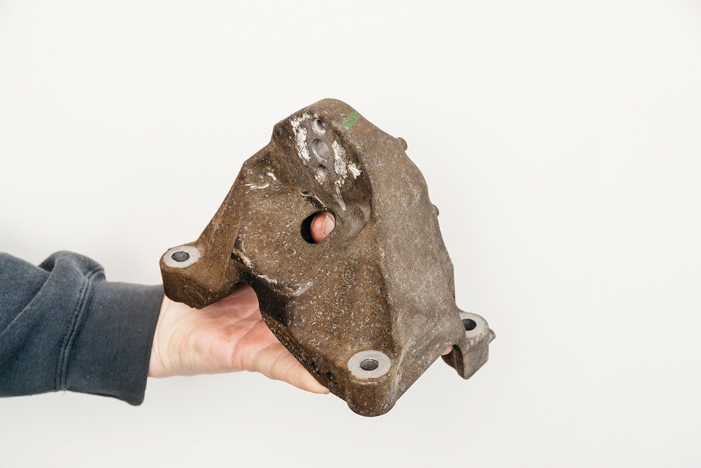
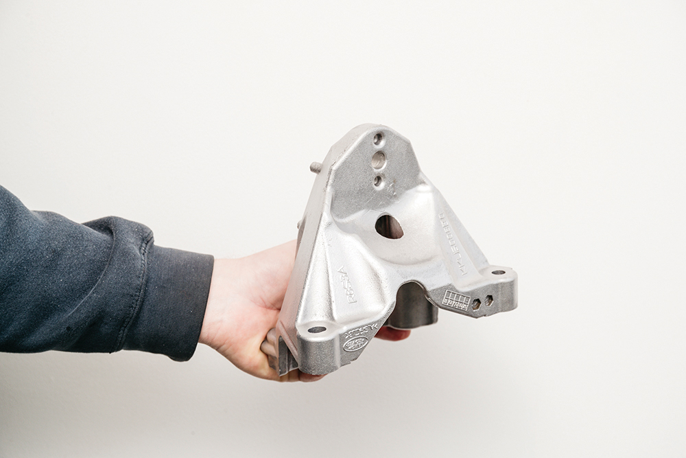
Why vapour blasting? Before and after of an engine mounting bracket that was vapour blasted. The process polishes as it cleans. Ideal for making aluminium parts look cosmetically as new.
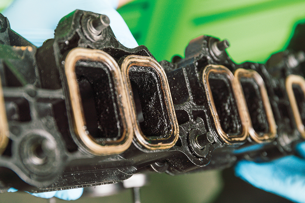
Internal prep work: This inlet manifold will also need cleaning internally. This crud build-up is typical, but it’s unseen unless the manifold is removed. Any sensors will benefit from a clean, too.
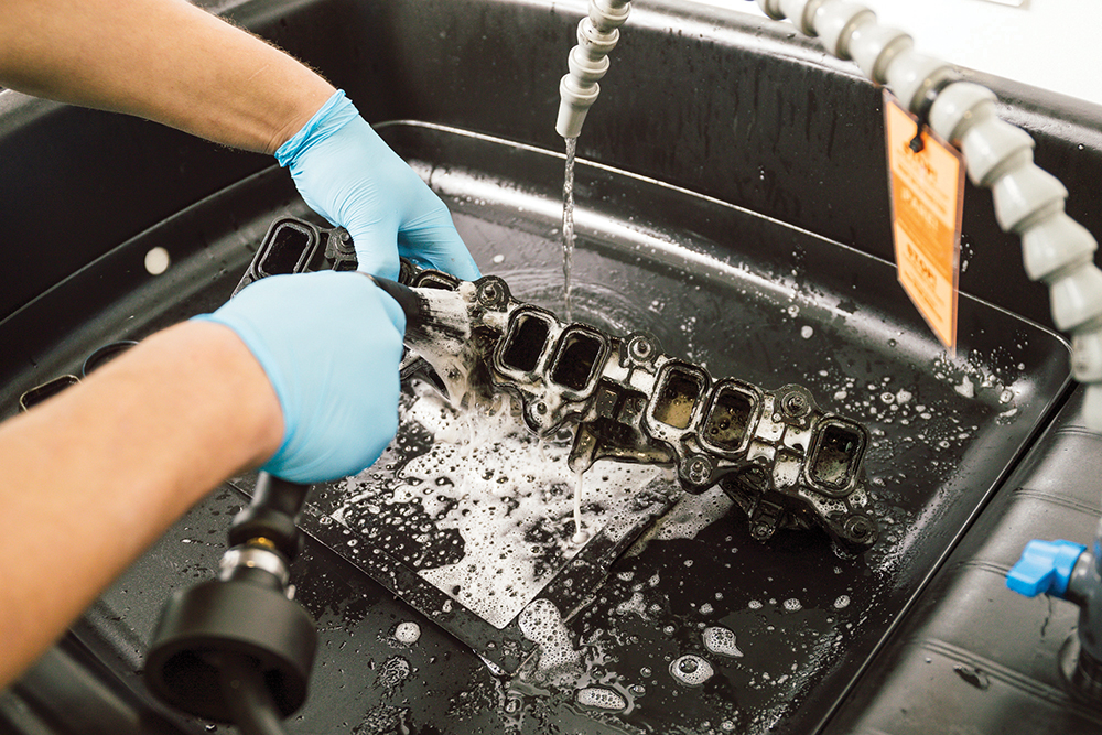
Scrub-a-dub: This eco-friendly parts washer is water-based. It works by bio-remediation: micro organisms (rather than solvents) break down the removed crud. It still takes plenty of scrubbing though.
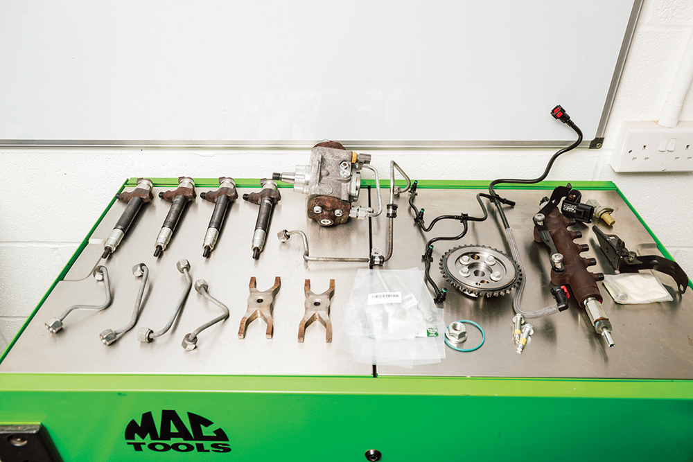
Cleanliness is key: These refreshed parts and new components and fixings are ready to fit. Note the clean, organised work area. The room also has its own set of spotless tools.
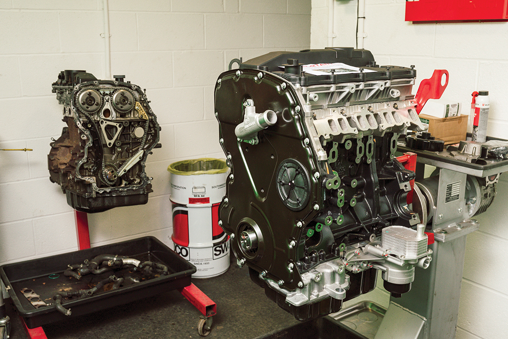
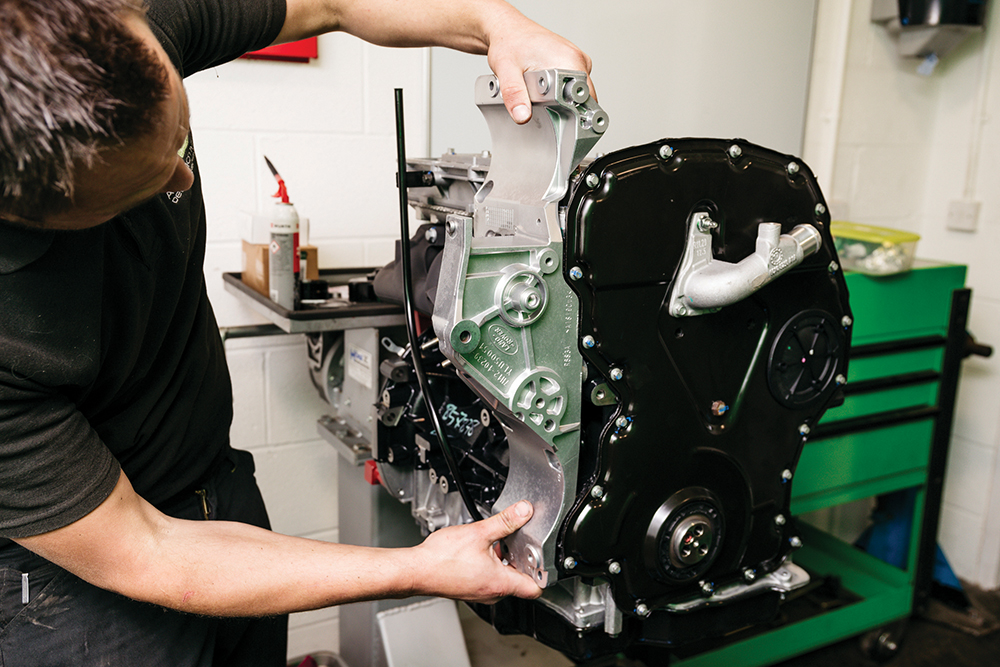
Time and space: The new engine is mounted on a stand with the old engine standing nearby. We have plenty of space, and plenty of light. All these details matter.
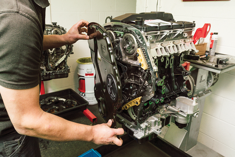
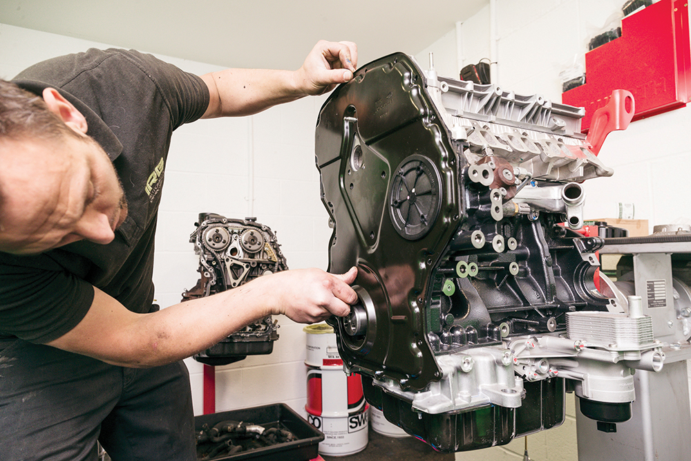
First step: The engine comes with a timing cover, but not sealed down. First step is unbolting that to access the timing chain behind it later, which will be slack.

Chain tensioner: The new engine’s automatic chain tensioner has a pin fitted to prevent the black tensioner arm here exerting force on the chain while the timing is being set.
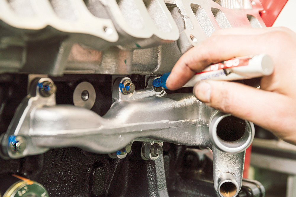
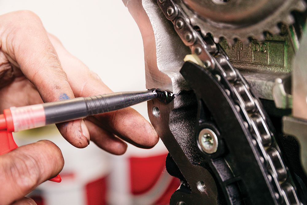
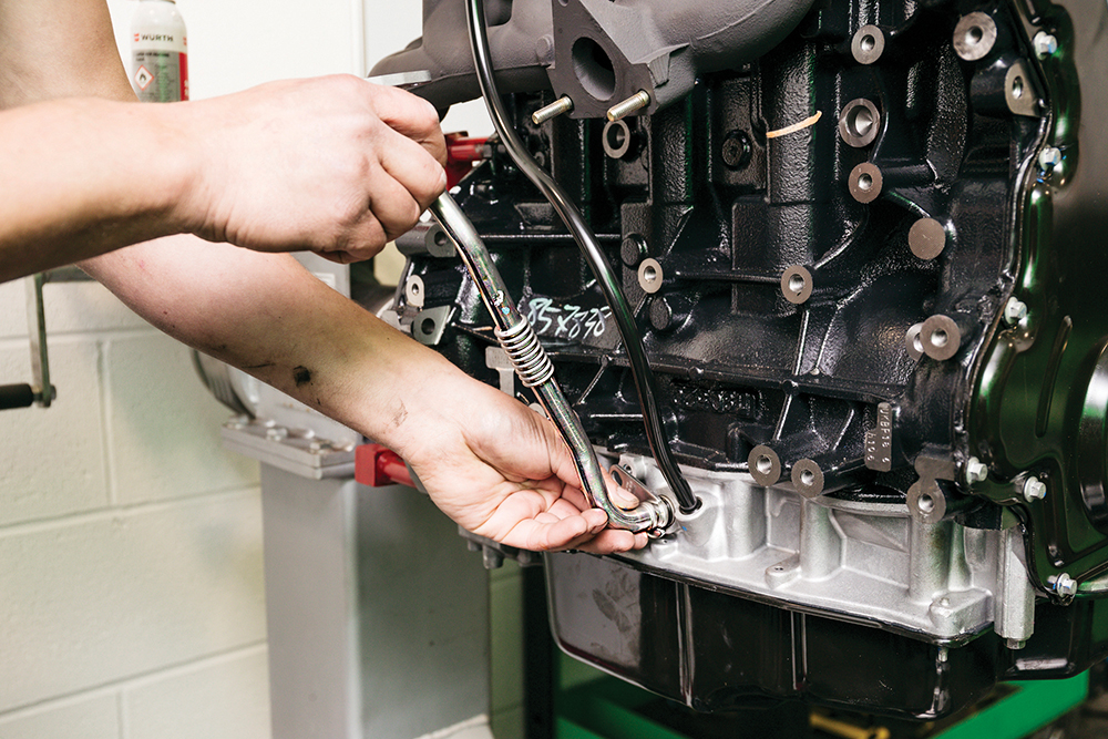
Water inlet: Refit the water inlet and gasket. Accurately tighten the fixings using a torque wrench, then apply a paint pen: paint on a fixing confirms it is correctly torqued.
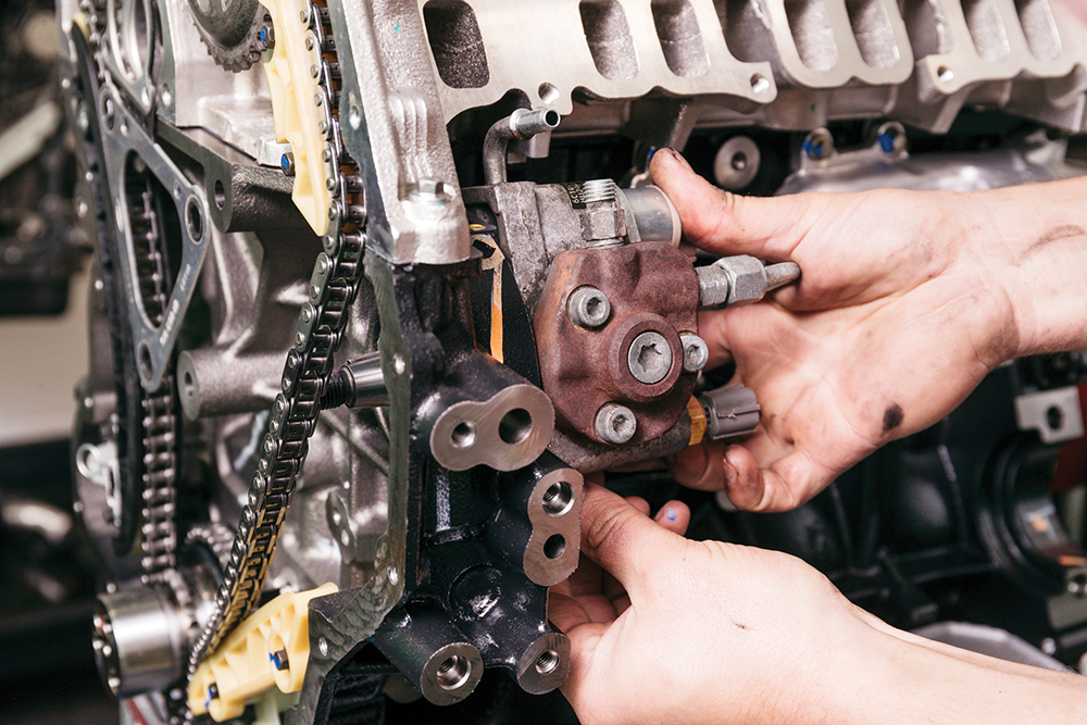
Fuel pump: The original fuel pump is reused, fitted with a new O-seal on the mating face, then bolted to the engine. Fixings are torqued to 23Nm and paint-marked.
Working on engine timing
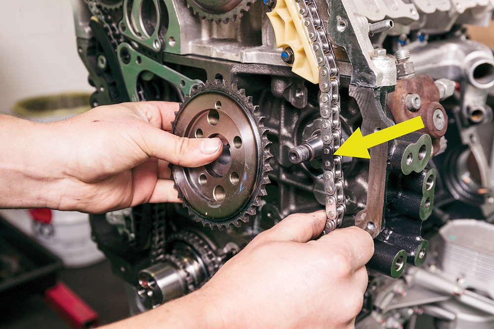
Timing matters: The pump pulley is fitted. Note the black chain links: there are three (one arrowed) at precise points which are used to set the timing against each sprocket.
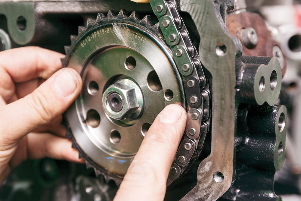
On your marks: Position the pump sprocket on the fixing holes, but don’t fit the bolts yet. Line up this indicated position hole on the sprocket with the black chain link.

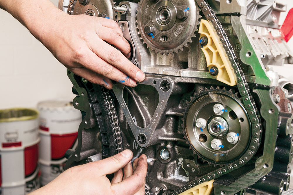
Timing pins in: Camshaft sprockets have been positioned with timing pins located through them (bottom), and black links in the chain aligned with arrows on sprockets (top).

Special crankshaft tool: This crankshaft locking tool is fitted onto the crankshaft end to prevent it rotating. A spigot on the arm of the tool engages a hole in the cylinder block.
Timing the engine

The chain started out slack on the new engine, until the fuel pump was fitted. Now we need to confirm the correct chain and sprocket positions which, in turn, set the timing of each component in relation to the others. The timing pins lock the camshaft sprockets in the correct position, the crank tool locks the crankshaft in position, and the black chain links and sprocket marks are then used as reference to set the chain. Note that all this is done with the rocker carrier loose, because spring pressure on the rockers could force the camshafts out of position.
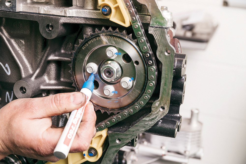
After fitting the fuel pump sprocket fixing bolts, but not tightening them fully, ensure the black chain links line up with the three position markers, that is: the arrows at 12 o’clock on the two rocker sprockets and the hole in the fuel pump sprocket (all marked by red dots on the photo).
We had an issue after first lining the chain up, whereby the crank locking tool couldn’t align with its locking hole in the cylinder block. Double checking and working through each element confirmed we were one sprocket out at the crank. This was corrected by ensuring chain slack all sat between the crank and exhaust sprocket (top left), so as to be later taken up by the tensioner arm. We now have the crank, camshafts and pump set in the correct positions relative to each other and the chain, so we can now withdraw the pin from the chain tensioner thus, correctly tightening the chain.
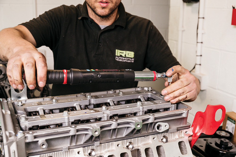
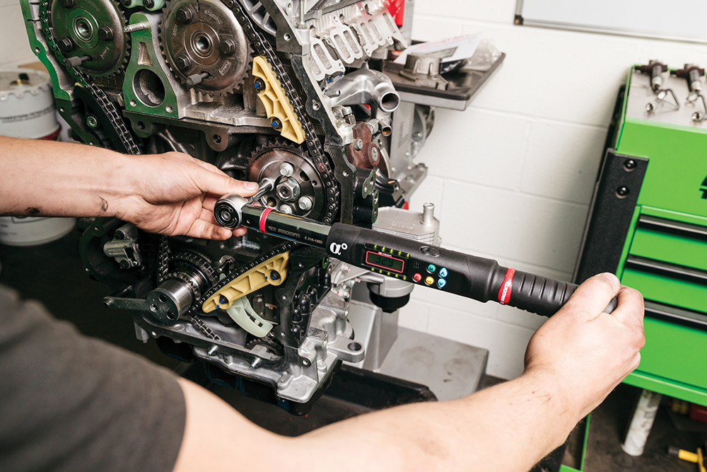
Torque the fixings: Torque the rocker carrier fixings. These are 30Nm, plus 30 degrees. A high tech torque wrench does both in turn, with lights and sounds to confirm each.
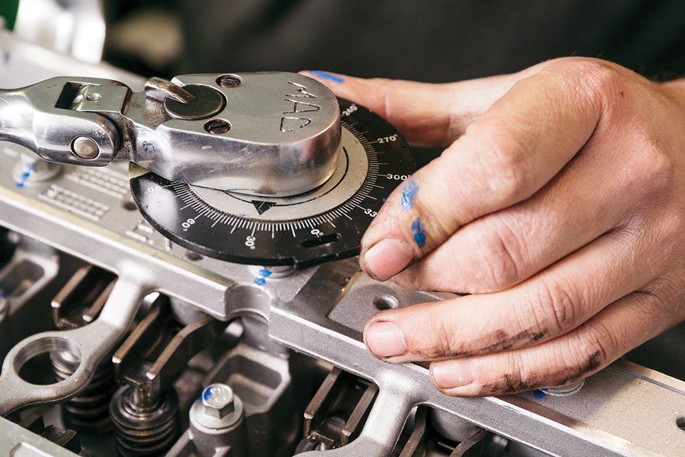
Just as good: Equally viable is the old method of using an angle gauge after the torque wrench. This fits between socket and bar (not torque wrench), allowing manual degree measurement.
Tightening sprocket bolts: The timing sprockets have fixings in, but aren’t tight – or are they? The fuel pump is torqued to 33Nm, the cams to 35Nm. Next, the lesson for using paint pens.
This is why: Torque it, dab it – paint instantly confirms the fixing is tight. No paint? Then the fixing is assumed loose. It is a very useful practice during engine building.
Vital fluid: Before rotating the engine to confirm the timing is correct, the lash adjuster rollers on the cams need to be lubricated with engine oil, as best practice.
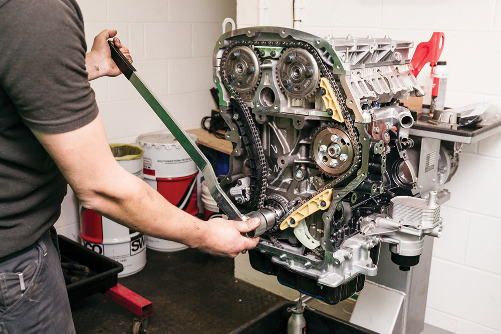
The moment of truth: With the timing pins removed, and using a long bar and the special tool to hold the crankshaft, the engine is rotated twice. Turning steadily, check you can’t feel components fouling internally. After two full turns, check that the timing pins will drop straight back in to the middle of their slots (not tight to one side) and the black chain links line up again against their markers. If they don’t, undo the sprocket fixings, reset the timing, rotate the crank twice, recheck.
Continuing the build-up
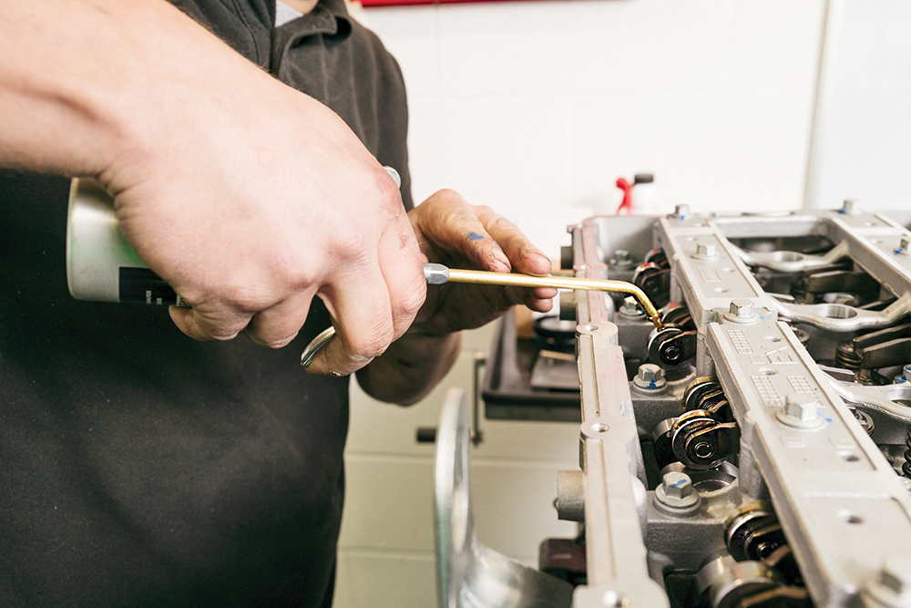
Moving on: We can now refit the timing cover. First, the joints between block and head need sealing. A 3mm bead of RTV sealant is neatly applied on each joint.
Hidden gasket: Fit the water outlet’s triangular gasket. The timing cover now needs sealing to be oil-tight, and a special tool used to correctly align it for the crank seal.
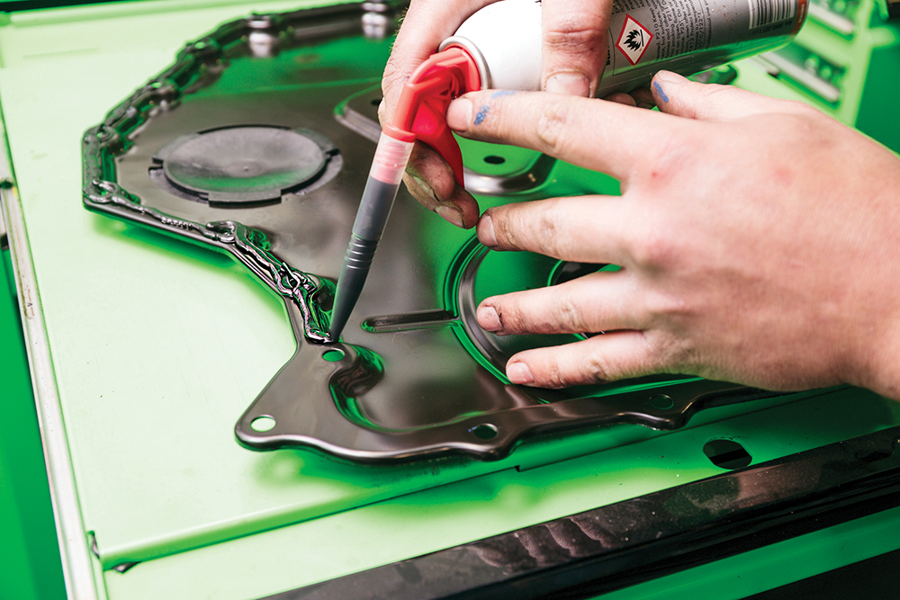
Proper seal: Apply a 3mm bead of RTV sealant around the timing cover mating face. Ensure you loop around the circumference of each fixing hole, too, to ensure oil-tightness.
Fit, but not fully: Fit the timing cover in position with the fixings, but leave them loose. Now we use the cover adjustment tool, which locates the cover accurately against the crank.
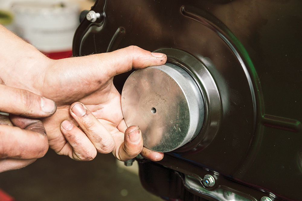
Locate it: The tool locates everything in one go. Once located, tighten the fixings for the timing cover and remove the tool. Next is the seal, needing another special tool.
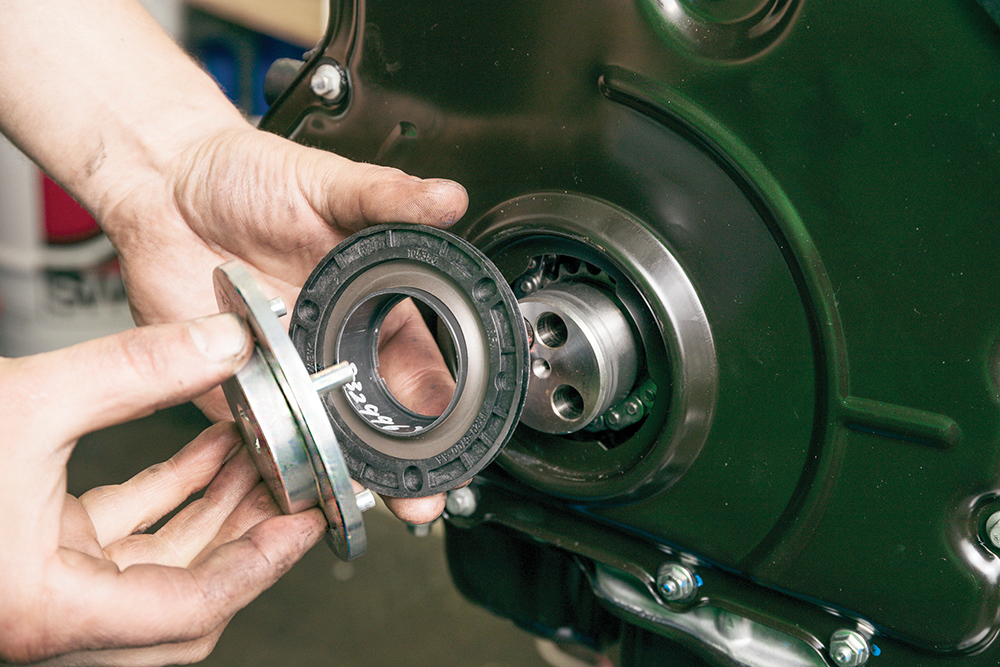
Push, turn: The seal pushes on into position then rotates, which is where the special tool comes in. By rotating it, this locates three locking tabs against the timing cover.
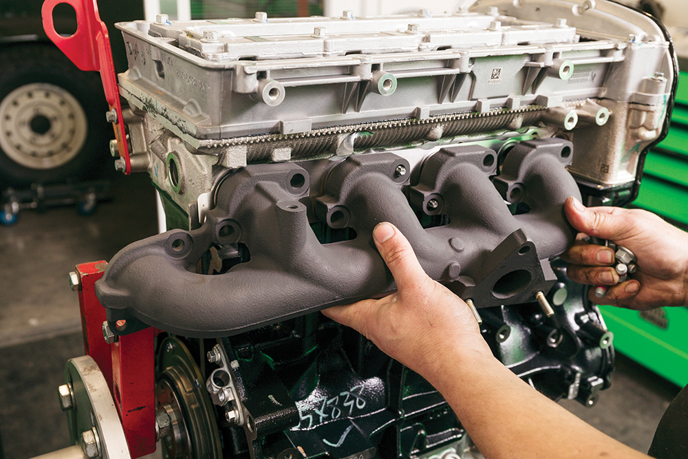
Old, but looking new: Now we continue fitting other ancillaries. The vapour-blasted original exhaust manifold has been painted with high-temperature paint. On it goes with a new gasket, looking superb.
Mount up: The air con bracket goes back on. Not so long ago these were filthy from the scruffy old engine. Vapour blasting gives them a new lease of life.
Forging ahead: The dipstick tube is a simple push fit. Then the turbo oil drain bolts to the block. Again, the turbo drain is from the old engine, blasted clean.
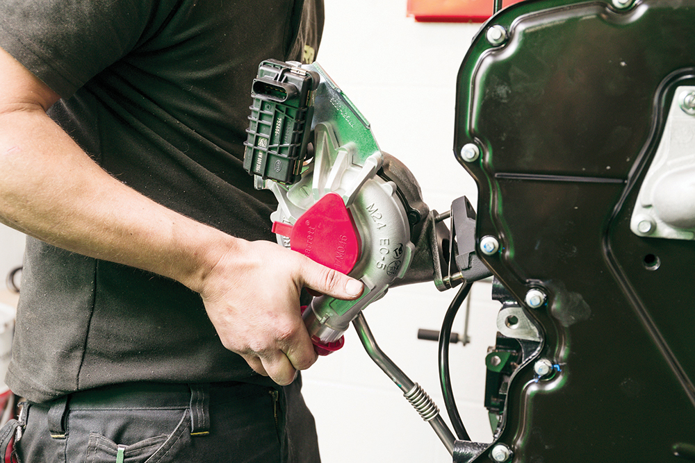
Big bits go on: On goes the new turbo and gasket, remembering the small gasket underneath for the oil drain and taking care not to knock it off.
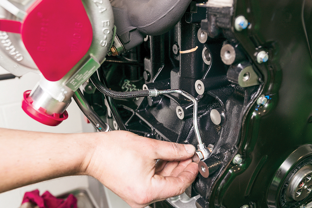
Never reuse this: A new turbo oil feed pipe goes on. Never reuse an old pipe with a new turbo, so you don’t risk introducing any contaminants to the new bearings.
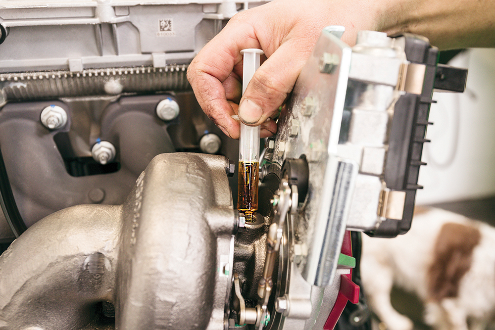
Top tip: Using a syringe, pre-load the turbo oil feed with engine oil to ensure a swift supply of oil on the all-important first start-up. An important detail.
Coming next in part 3, we'll fit the fuel system, various engine ancillaries from pulleys to sensors, and we’ll swap the standard sump for the special Defender part.
LIKE TO READ MORE? Try our Budget Digital Subscription. You'll get access to over 7 years of Land Rover Monthly – that’s more than 100 issues plus the latest digital issue. The issues are fully searchable so you can easily find what you are looking for and what’s more it’s less than 10p a day to subscribe. Click here to find out more details and start enjoying all the benefits now.