


30 January 2024
|
 Carb kitset: All parts cleaned and ready to fit
: credit: © Alisdair Cusick
Carb kitset: All parts cleaned and ready to fit
: credit: © Alisdair Cusick
The carburettor is vital to petrol engine efficiency and good running. Alisdair Cusick reports on a professional carb restoration
Need to know
Time taken: 4-5 hours.
Tools needed: Soft-jawed vice, pillar drill, piloted reamers, jet gauges, file, hacksaw, disc sander, screwdrivers, pliers, plate glass, ultrasonic cleaner, taps and dies, polishing wheel, 400 grit wet and dry paper.
Difficulty: 2 out of 5
Models: All Series I models, through to Series IIA, but principles are the same for any carburettor.
Parts used: Carburettor as supplied, Fuggle’s Fettling, £40/hour.
Work Safely
• Use the right tool, for the right job.
• Use well-fitting tools on soft brass parts to avoid distortion.
• Get an expert to do the job, if in you’re any doubt.
• Never take risks with heat or pressure.
• Wear breathing protection when cutting or handling aged materials which may create a dust hazard.
• Gaskets may contain asbestos.
Thanks to: Martin Lawrie of Fuggle’s Fettling for his help with this feature, 07950 335835, fugglesfettling.co.uk
Poor starting, rough idle, hesitation, black smoke or poor fuel economy; all these issues suggest one cause on classic Land Rovers: the carburettor. A common component, but one that does a complex task, namely balancing the mix of air and petrol for all throttle demands.
That balance is a fine one and, with passing years, inevitably comes the need for a carburettor rebuild. Rebuilding a carburettor is a relatively straightforward job, typically requiring a methodical strip down, clean, then reassembling with new fibre washers and gaskets. For a carb in good order, that usually revives it, but with some being 75-years old, other more involved issues arise, meaning the task often entails correcting warpage of mating faces, replacing jets, or re-bushing worn throttle spindles. Carburettors are usually made of Mazak, an alloy that can be prone to stripping threads, or cracking, most typically at the emulsion tube holder. Fixings can be a mix of Whitworth, AF and metric, occasionally with one type of head and a different thread.
There’s an art to carburettor set-up and, whilst there was once always that local garage nearby who understands them, those skills aren’t easy to find today. Because of this, there are a scarce few specialists who have become the go-to for a thorough job. One of these is Martin Lawrie, of Fuggle’s Fettling, renowned for his work on Solex and SU carbs in particular. Rebuilds now often incorporate complete restoration, so he not only rebuilds the units, but can also visually refresh them to as-new condition.
He walks us through a typical process of restoring a Solex 32 PBI-2 from a Series I, though the basic principles are broadly the same for a Series IIA B40PAIO-5A and the Series III’s Zenith 36IV, Stromberg and SU carburettors.
How it works
Looking at the downdraught carburettors used on Land Rovers, first is the float chamber, which is nothing more than a fuel tank for the carburettor, supplying fuel to the emulsion tube. The fuel pump delivers fuel into that float chamber and, as the level rises, a hinged float touches against a needle valve, shutting off the fuel supply to the chamber. It’s a similar principle to a toilet ballcock. As fuel is used, the level (and float) lowers and the needle valve re-opens, thus constantly maintaining the crucial float height, and therefore fuel supply to the emulsion tube.
Parallel to this, sits the carburettor throat: a large circular hole through the carb where air enters at the top (drawn in by the suction created by the engine’s pistons on their intake strokes), and air-fuel mix is delivered at the bottom into the intake manifold. Jutting into the throat is the emulsion tube (which is nothing more than an outlet sitting in the middle of the throat), a venturi and, below that, the butterfly valve of the throttle plate.
Fuel sits in the emulsion tube at the same height as in the float chamber. As the engine runs, air enters the carb throat and passes through the venturi which constricts the air, creating negative pressure downstream, thereby sucking in the fuel from the emulsion tube. The fuel becomes atomised in the carb throat where it mixes with the air at a theoretical ratio of 14.7 parts air to 1 of fuel (known as the stoichiometric mixture), though the mixture will vary according to tuning and running conditions. The fuel/air mixture then enters the intake manifolds from where it’s drawn into the engine cylinders where the spark plugs ignite it in the correct sequence to drive the pistons and rotate the crankshaft.
An engine needs to rev above idle speed though, and that is where the throttle plate comes in. As the throttle is depressed, the throttle butterfly opens in the carb throat, allowing more air in, in turn sucking more fuel in, thereby engine revs increase.
The accelerator pump is an additional circuit linked to the throttle plate. Under rapid throttle increases, the accelerator pump squirts in a measured amount of extra fuel straight above the venturi. Being before the vacuum is formed, this enrichens the fuel mix ahead of the emulsion tube, aiding the engine to accelerate.
Dismantling the carburettor

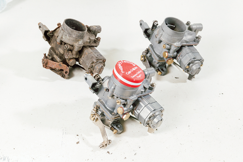
Starting point: A typical starting point. This 32-PBI-2 is dated 1965, but the type was used from 1948, with different jets for the two 1600cc and 2000cc Series I engines.
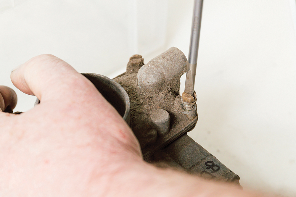
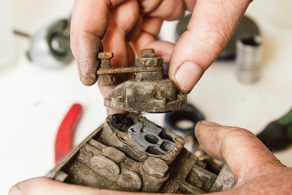
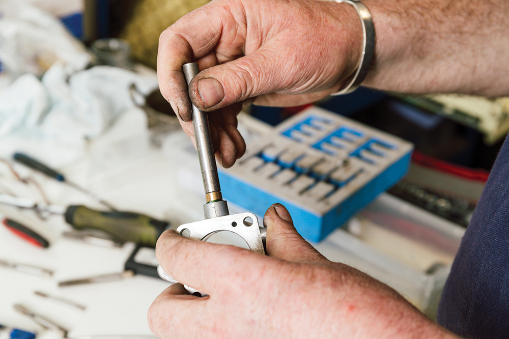
Get the best grip: Martin begins by unbolting the fuel inlet, then unscrews the top cover. Whether bolt or screw head, well-fitting tools are a must, to avoid damaging them.

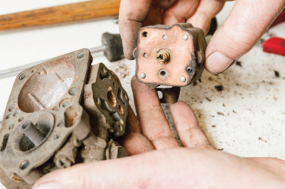
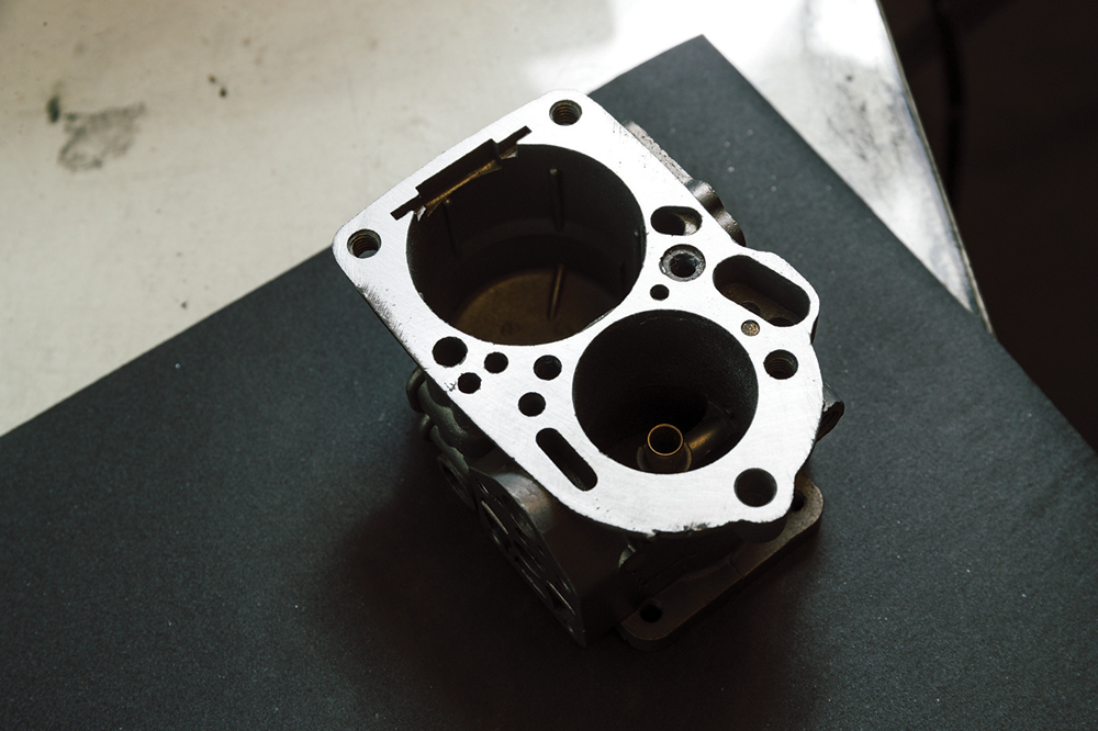
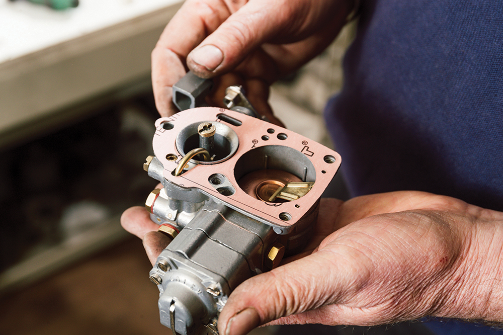
To business: Cover off, we see the internals: float chamber, carb throat with accelerator pump injector and emulsion tube holder. Upper gasket may contain asbestos.
Deciding whether to rebuild, or repair
In the past, a straight rebuild and clean did the job, but often a carb can be worn, meaning repair work is needed. Check the flatness of the body and top cover on a flat surface. Warping means gaskets can’t seal and unwanted air is sucked in, weakening the mixture, or fuel can leak internally. Hold the throttle spindle end and check it for play. Minimal play is acceptable, but frankly, if you can feel it wiggle, re-bushing the body is the only way to cure that wear properly. Similarly, examine the accelerator pump rod. Play in either end requires replacement parts to cure.
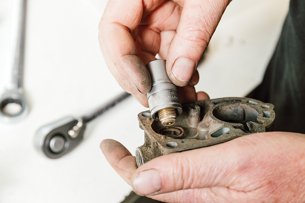
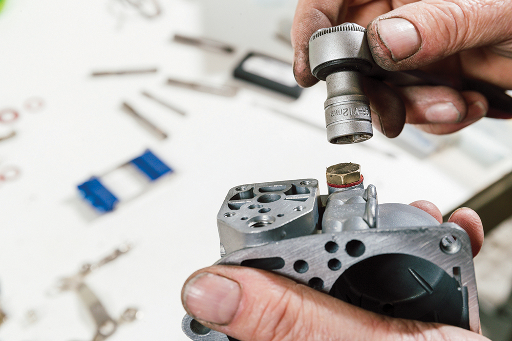
Strip down: Martin begins by unbolting the needle jet in the top cover using a socket spanner. The fixings are metric, but may not have the usual thread pitches.
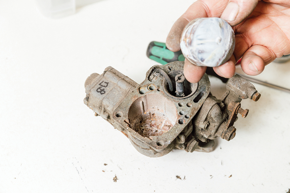
Remove, but store: Removing the float shows a build-up of gunk, likely from stale fuel. Nonetheless, this will clean up. Store everything methodically as you remove it.
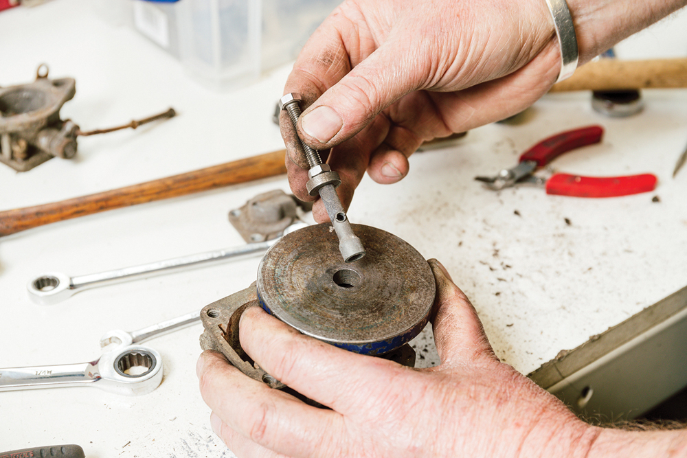
Pulling it breaks it: The pump injector is unscrewed. Martin taps that screw hole to M5, then threads in a bolt to wind the assembly out, working against the carb body.
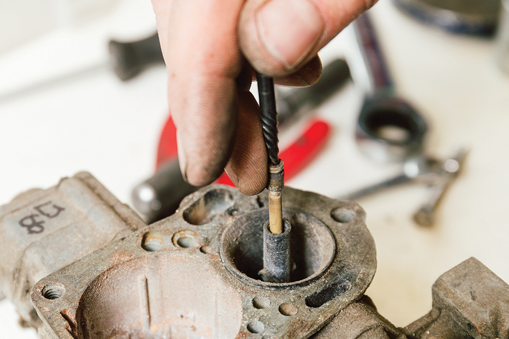
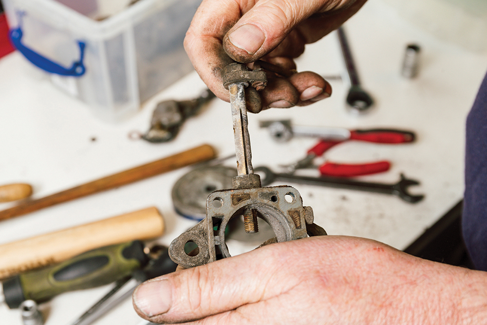
Take care: Commonly, the emulsion tube holder cracks if the air correction jet was overtightened. This comes out nicely. Use a stud extractor to pick out the emulsion tube.
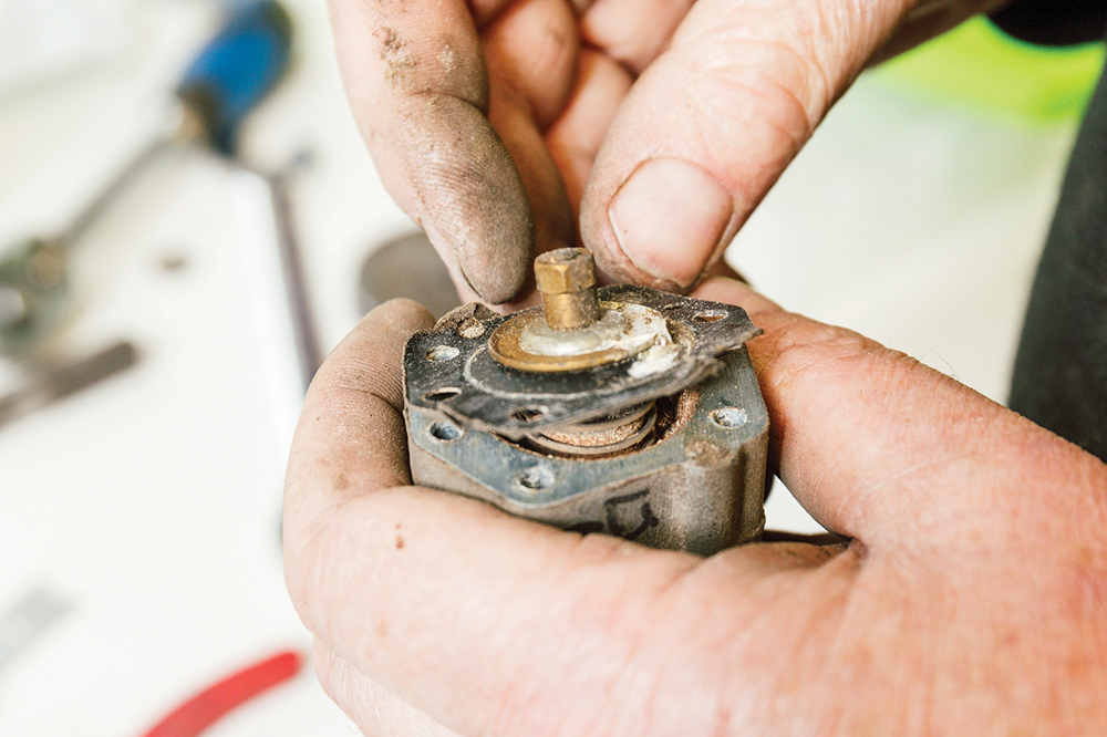
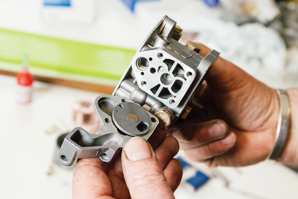
Bi-starter: The starter assembly, held by four long screws, is removed. Again, a well-fitting tool is essential. Inside, we see the various internal passages for fuel and air.
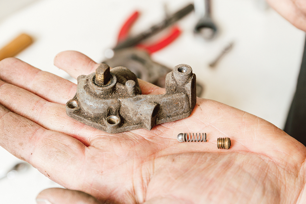
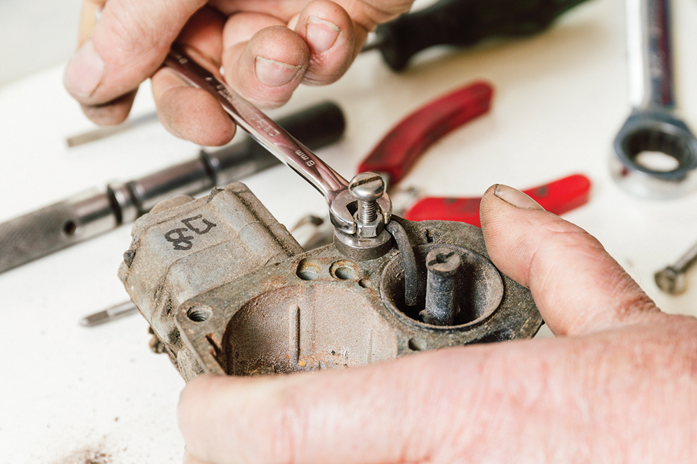
Remove, strip down: The starter detent ball, spring and retaining plug are removed, along with the choke cable arm. A ¼-inch Whitworth head on the fixing, but 8mm metric thread.
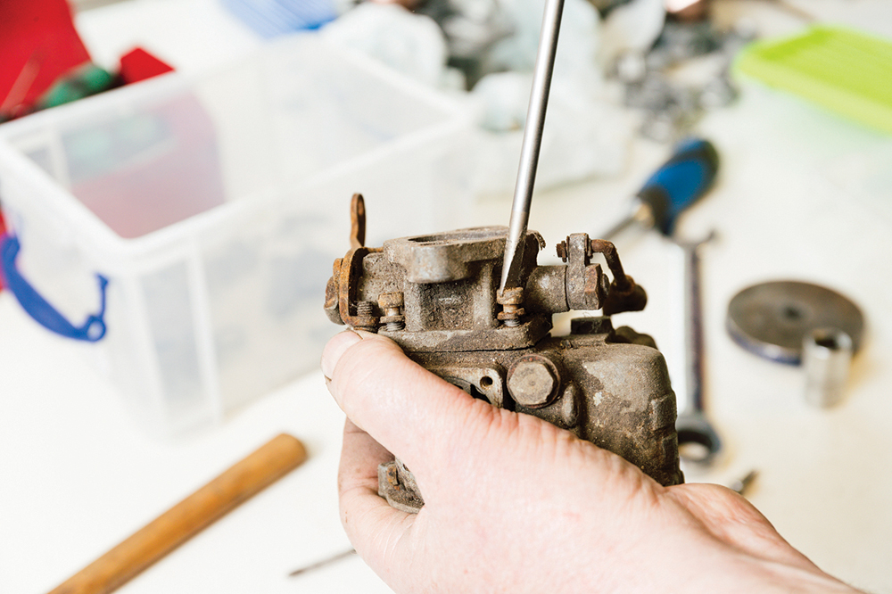
Throttle plate: Martin undoes the throttle plate, held on by four screws, and removes the throttle assembly as one. Keep everything, making notes or preferably taking photographs from various angles.
Pump off: Similarly, he removes the four accelerator pump-to-body screws (seen at the corners). Then the remaining two screws holding the pump body to the depression pump body are removed.
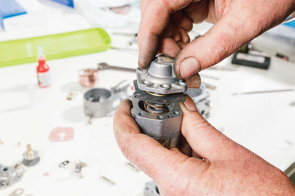
Break it down:He then strips the pump, removing the pump cover, then splitting the two bodies to reveal the diaphragms. There are springs inside. It may suddenly push apart.
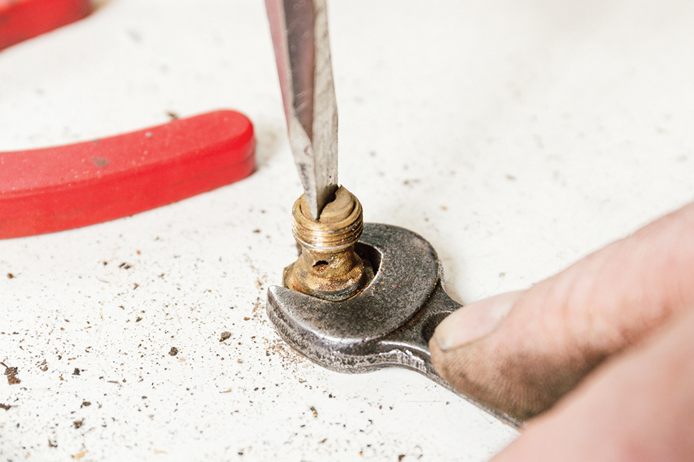
Jets out: All the brass jets are then unscrewed. Penetrating oil can help stubborn ones, as can working the fixing thread back and forth. All can potentially strip or shear.
Main jet: To remove the smaller jet inside the main jet, Martin holds it in a spanner on a table and unscrews the smaller jet. A vice could distort it.
Butterfly: Martin then moves to the throttle butterfly, first removing the two fixing screws, sliding out the butterfly, then withdrawing the spindle. Inspect for wear on body and spindle.
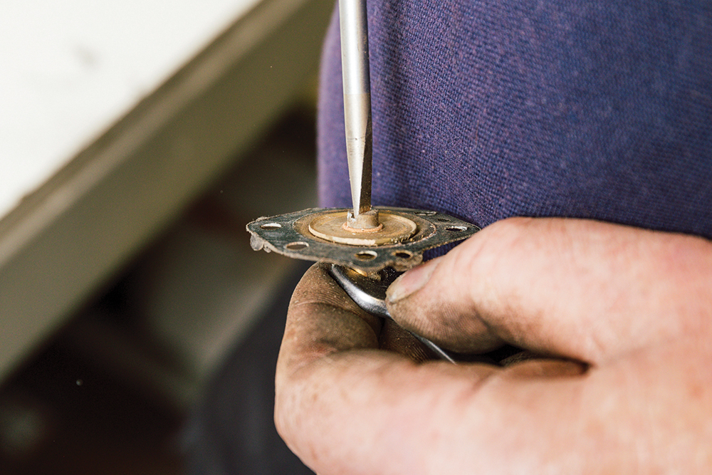
Pump parts: Next, the pump diaphragms are stripped of their spindles, nuts and washers. Note both the order and orientations of each as you strip them. The nuts are BA.
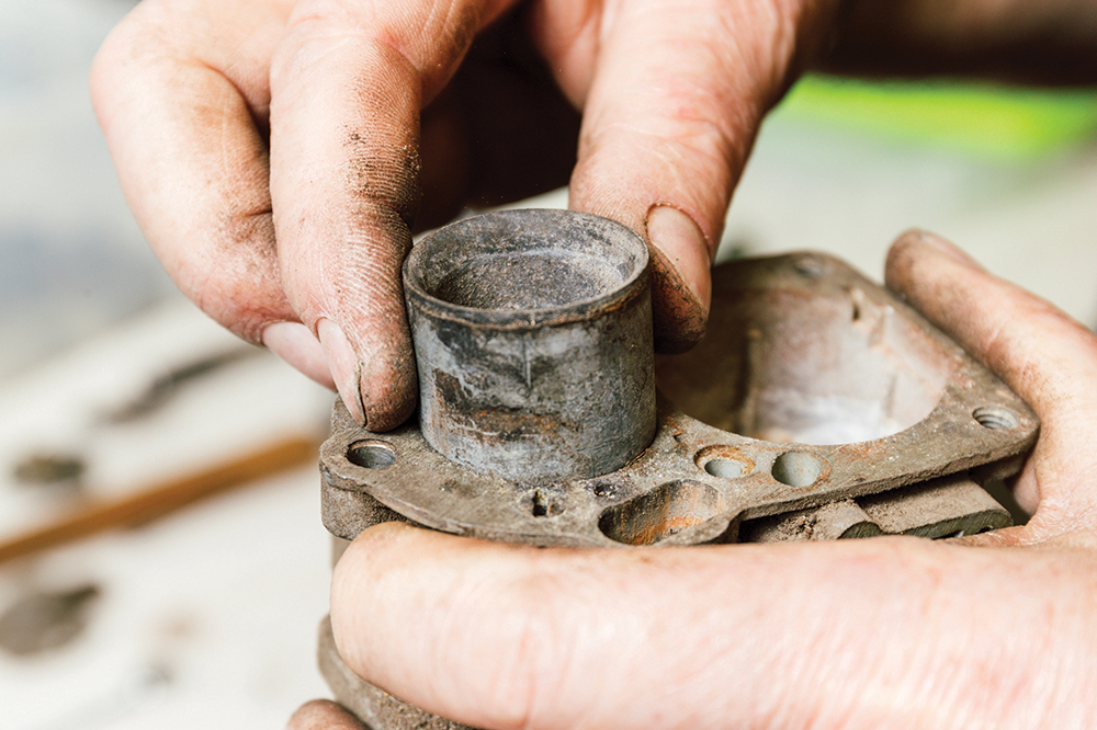
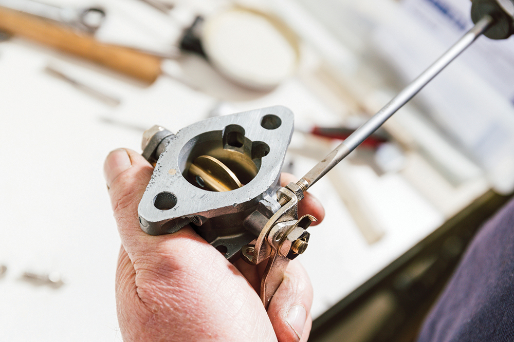
All out: Back on the body, Martin removes the venturi tube, knocking it upwards with a drift. It needs to come out so that the top face has no obstructions.
Fragile part: Martin then removes the emulsion tube holder by threading a bolt into the tube, then winding it out against the carb body. He makes the job look easy.
That, then is the strip-down. Each brass part is now cleaned in a proprietary wash process and ultrasonic cleaning is used to ensure all internal passages are clear, before checking all the jet sizes are correct. Jets rarely wear, but can clog, and it isn’t uncommon for people to drill jets larger in an attempt to cure running issues. The Mazak parts can be vapour blasted (an abrasive material carried in water) which will clean and polish the parts to as-new condition.
Alternatively, for a ‘war finish’, Martin bead blasts the components (dry media delivered by air) which cleans without polishing. Brackets and screws can be replated. A quality rebuild kit comprising new fibre washers, diaphragms, gaskets, needle valve, spindle and butterfly is also required.
Rebuilding the carburettor to restored condition

Carb in kit form: All the parts are prepared ready. Bodies cleaned, steel parts replated, brass parts cleaned and polished. But Martin has a couple of crucial further steps, for correct operation.
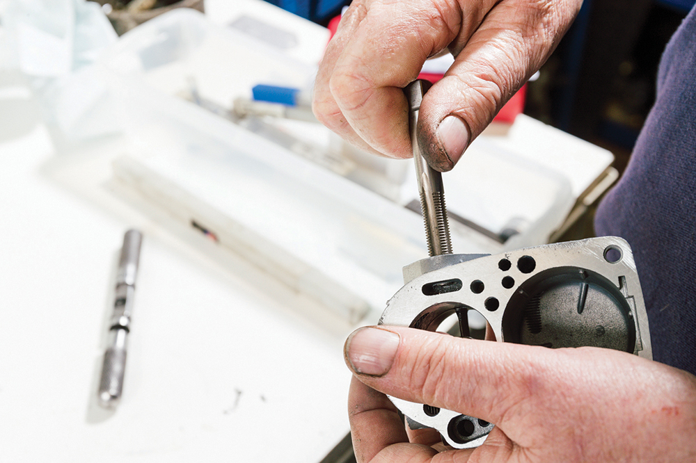
Tidy up: A tap of the correct size and thread profile is run down each screw thread. This sharpens up any thread damage, but also removes blast media and corrosion.
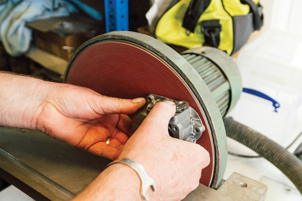
Flattening the curve: The carb bodies commonly warp. To correct this, Martin decks each mating face flat. For speed, he starts with a few careful passes on a bench disc sander.
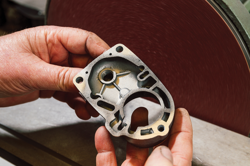
Tops, too: The warpage can create a vacuum leak, causing a lean mixture. The carb top also gets the same treatment. Note the high spots visible on the corners now.
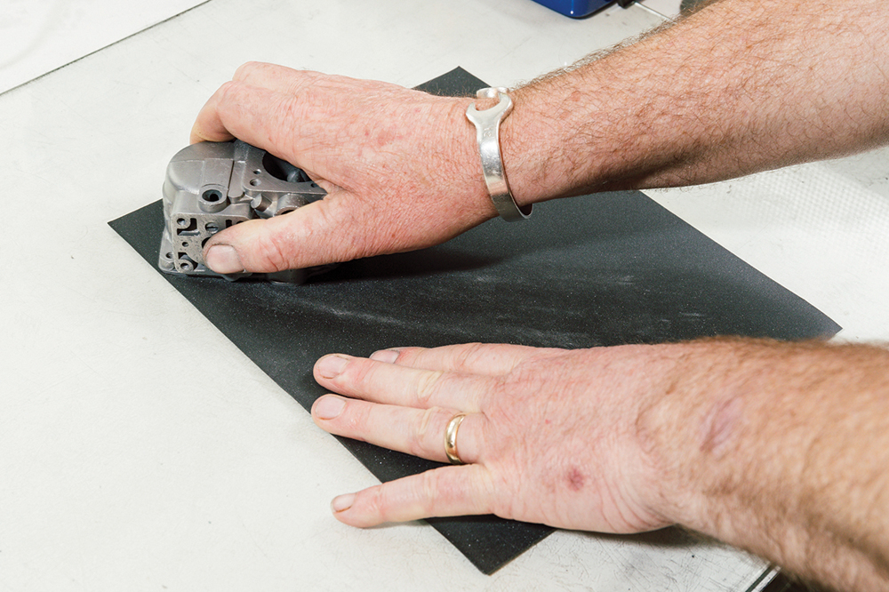
Finesse: The process is finessed using 400-grit wet and dry paper on sheet glass. He can now control the cut rate, regularly checking until the face is flat.
Good as new: The end result is a perfectly flat mating face. He repeats this for the throttle body and top cover, ensuring air- and fuel-tight seals on the carb.

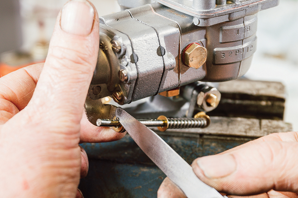
Size check: Jets are all checked for correct size using a measure. They’re measured in millimetres. So a ‘75’ stamped jet will be .75mm, and a ‘135’ will be 1.35mm.
Jets in: Martin then fits a new fibre washer from the rebuild kit to each jet, and fits them to the carb. They want to be tight, but not over-tightened.
Accelerator pump: The pump diaphragms are assembled with two membranes per diaphragm and noting their correct orientation. Those then get sandwiched between the two pump bodies, with the correct springs.
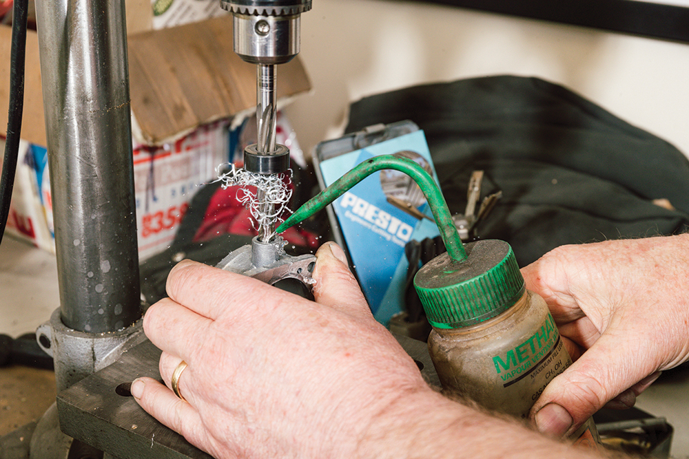
Extra skill: To cure play in the throttle spindle, Martin specialises in re-bushing the throttle body. Using a special piloted reamer, he drills the throttle body, perfectly in line.
Drilled to re-bush: He drills to a measured depth (leaving 3-4mm to avoid breaking through to the venturi), then inserts his specially-made brass bushes with a dab of thread lock.
Starter section: Whilst the thread lock cures, Martin builds up the bi-starter, ensuring the correct orientation of the disc. The detent ball should notch, but may be too worn.
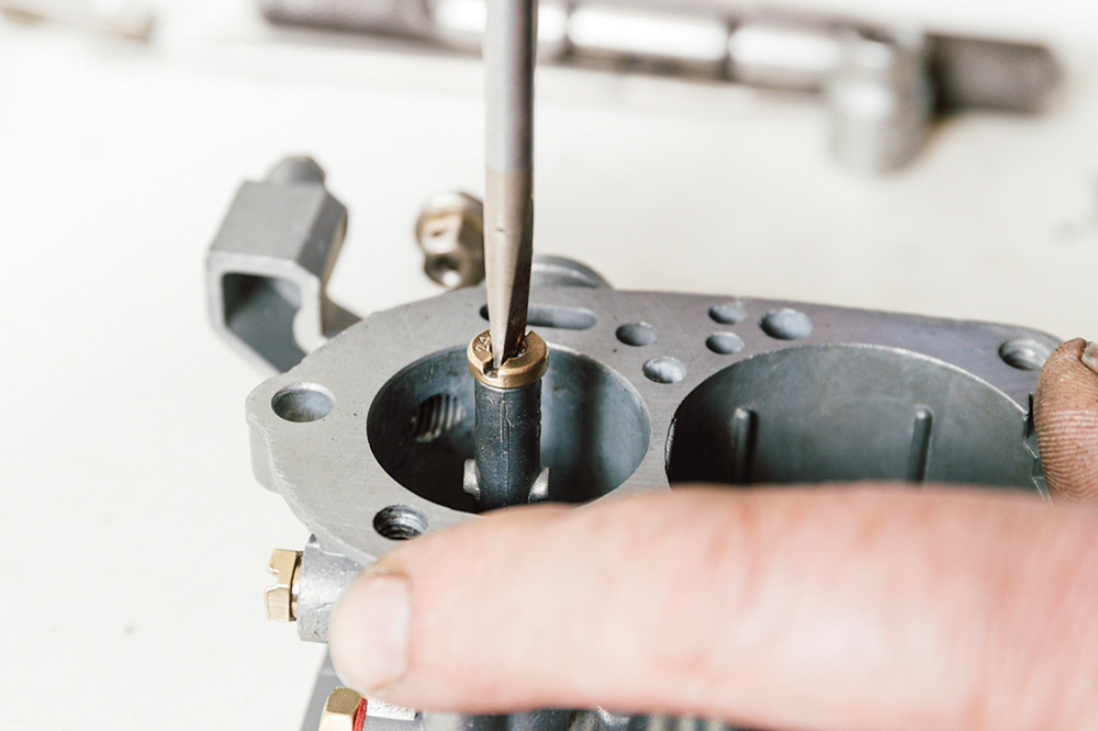
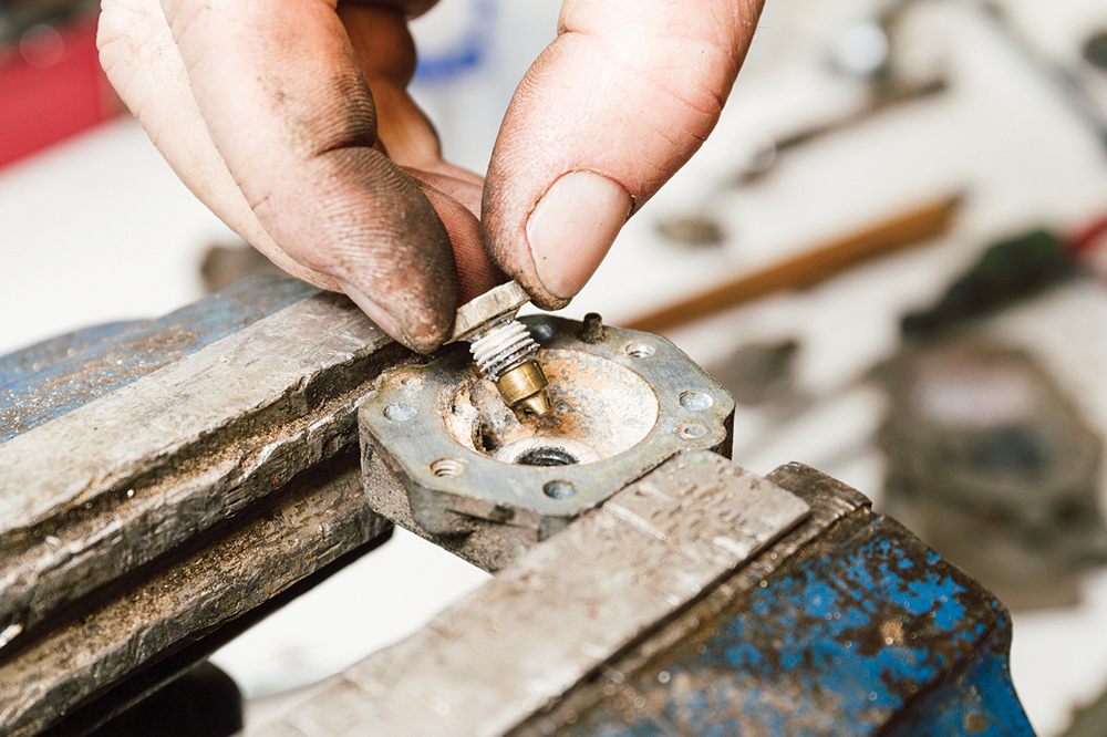
Don’t crack the tube! Martin refits the venturi, emulsion tube holder, emulsion tube and accelerator pump injector. The air correction jet is seated, but not over-tightened, to avoid cracking the fragile tube.
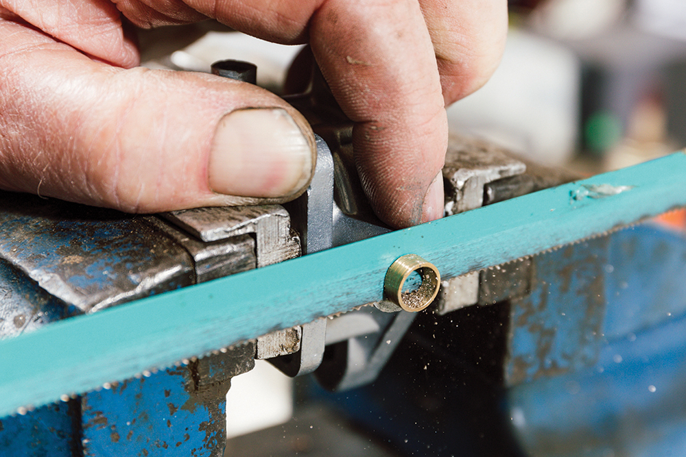
Back to the bushes: With the thread lock cured, the throttle body is held in a soft-jawed vice and the excess bush material trimmed back with a hacksaw, then filed smooth.

Reamed twice more: First, Martin uses a 5/16-inch piloted reamer to open out the bush internally, then repeats this using a long form 8mm reamer, matching a Solex spindle diameter.
Smooth as silk: New spindle in and tested for smooth operation. Throttle butterfly assembled and throttle lever assembly fitted, adjusting the idle speed stop screw.
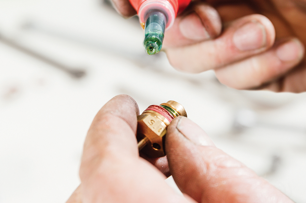
Modern fuel tip: Martin fits the new needle jet using an extra washer, as he finds that suits lower viscosity modern fuel. A dot of thread lock helps prevent it loosening.
Last job: Finally, he fits the float and toggle, the new top gasket, top cover and throttle body. Screws are measured to ensure they don’t bottom-out after the refacing.
Adjustments: The throttle stop screw and idle bypass screw are roughly set. On the car, they will need final fine-tune adjustment after the engine has fully warmed up.
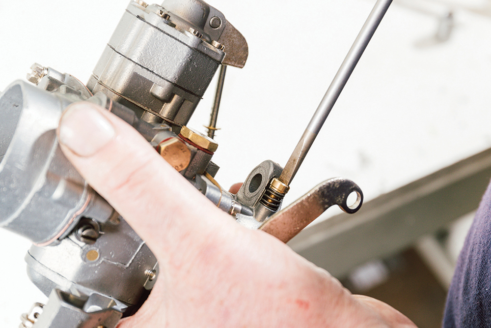
Rod gap: Martin’s final adjustment is to set clearance on the new replacement pump rod, which he manufactures. He also sourced replacements of the spring, crucially having the correct loading.
Final job: The end result is a component not just refreshed, but retuned to full mechanical health. Visually, we can choose perfection, or patina. Either way, it works as new.
Fuggle’s Fettling

Originally having worked in the medical industry, Martin Lawrie set up Fuggle’s Fettling after selling his medical diagnostics company. A lifelong tinkerer with classic cars, he continued his time-served methodical approach to vehicles as a business. Fuggle’s is named after his 1920 Talbot 14/45 pick-up, originally owned and converted by a Sunbeam, Talbot and Hillman dealer in Bushey Heath. Already signwritten as Mr R.F Fuggle, the name stuck. Today, he works on ‘anything fiddly’ with a knack for restoring original carburettors, wiper motors and electrical parts from Land Rovers and beyond. He also 3D-prints parts and tools, notably gearbox drilling jigs and main bearing T-seal guides for Land Rover Series vehicles.
Like to have your own Land Rover library?
Try our All-Access Digital Subscription. You'll get access to over 7 years of Land Rover Monthly – that’s more than 100 issues plus the latest digital issue. All issues are fully searchable so you can easily find what you are looking for and what’s more it’s less than 10p a day to subscribe. Click the link above to find out more details and start enjoying all the benefits now.