


28 January 2021
|
 The halfshafts on this 2012 D4 had suffered a hard life
: credit: © Dave Barker
The halfshafts on this 2012 D4 had suffered a hard life
: credit: © Dave Barker
CV joint noise in the front axle assembly calls for replacement driveshafts. Dave Barker explains how it’s done
As with other Land Rover models the Discovery 4 delivers drive to the front wheels from the front differential via a pair of front drive halfshafts: a long shaft on the right-hand side and a short shaft on the left. Each drive halfshaft has two constant velocity (CV) joints, one at each end, which allows for the suspension to move independently and the steering to turn while constant speed drive is maintained. The inner CV joint is engaged into the front differential and the outer CV joint is engaged into the wheel hub. Like other CV joints, both use a grease-packed cage of internal components that are protected by rubber boots to prevent the ingress of water and dirt. When the joints are worn or damaged, the best option is to replace the complete drive halfshaft.
After 83,000 miles this 2012 Discovery 4 developed a loud clicking noise from both sides of the front halfshafts while being driven and turning. It had suffered a hard life and, although the rubber boots on the shafts looked to be in good condition, they could still have allowed water into the CV joints, so it was decided to replace both drive halfshafts. It’s not an overly difficult job because they can be removed and replaced without completely removing the wheel hub assembly. However, the front wheels need to be off the ground and access is needed underneath the vehicle to pry the driveshafts out from the front differential.
When ordering drive halfshafts it’s important to also order the correct halfshaft hub end nuts, which are not supplied with the shafts. We’re starting the job by removing the right-hand side halfshaft first, though the procedure is the same for both.

We’re replacing the left and right-hand driveshafts, each being located between the wheel knuckle/hub and the differential. Each shaft assembly includes an inner and outer CV joint.
Removing the front halfshafts

With the front wheels off the ground and the steering turned, the loud clicking noise could be heard even when the front wheels were rotated by hand.

Once the Discovery had been securely lifted off the ground, the engine undershield which is secured by ten bolts was removed, then the front road wheels.

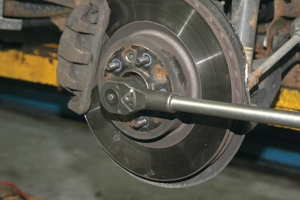
With the brakes applied to prevent the hub from rotating, the drive halfshaft hub retaining nut is undone and removed, this is very tight, requiring good leverage.

A soft face hammer and copper drift was used to knock the drive halfshaft back through the hub assembly (Land Rover recommends using a special tool).

Before the wheel knuckle is undone further, the brake hose and cable bracket’s securing bolt was removed from the knuckle.

Once the bolt was out, the bracket along with the brake hose and cable are removed from the wheel knuckle to prevent them from being over-stretched.

The securing nut that is holding the upper control arm ball joint to the wheel knuckle is next to be undone and removed.

With the nut removed, a suitable ball joint separator tool is used to split the ball joint, thus releasing the wheel knuckle from the upper control arm.

The steering tie rod end ball joint nut is removed and the ball joint separator separates the joint from the wheel knuckle without damaging the rubber boot.

Once the tie rod end ball joint has been separated from the wheel knuckle, the steering linkage tie rod can be released from the knuckle.

Using a pry bar under the anti-roll bar, the lower control arm is pushed down, allowing the wheel knuckle assembly to be released from the upper control arm.

With the wheel knuckle released from the upper control arm, and the steering linkage tie rod moved clear, the halfshaft is ready to be pulled free.

Working under the Discovery and using a pry bar, the end of the halfshaft going into the differential is gently worked out and released from the differential housing.

Now that it is released from the differential housing, the complete drive halfshaft assembly can now be pulled out and removed from the vehicle.

With the shaft removed, the full extent of the play in the CV joint could be felt, despite there being no signs of damage to the rubber boots.

This shorter left-hand drive halfshaft is removed in the exact same way as for the right hand. This shaft also had excessive play in the CV joints.
Fitting the new halfshafts
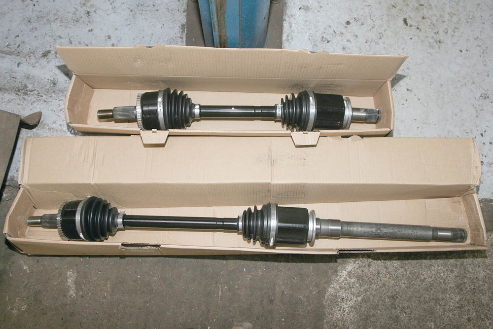
Here is the new right-hand shaft (bottom) and left-hand driveshaft (top). It’s also necessary to buy the correct hub nut and washer for each. 
With an assistant working under the vehicle, each of the two drive halfshafts are carefully fed between the steering components towards the differential housing.

After first aligning the splines of the drive halfshafts with those of the diff, the halfshafts are pushed into position (splines were treated with anti-seize grease).

In a similar manner, the splines at the inboard ends of the halfshafts are coated with anti-seize grease, aligned, and pushed home into the wheel knuckle hub assembly.

Once both ends of the drive halfshafts are correctly aligned, the wheel knuckle hub assembly is pushed in and the driveshaft pushed into position.

The wheel knuckle is refitted to the upper control arm ball joint and the retaining nut tightened, pulling the knuckle fully into position, then torqued to 70 Nm.

After refitting the brake hose and cable bracket, the tie rod end ball joint is refitted into the wheel knuckle and its nut tightened to 76 Nm torque.
A new drive halfshaft retaining nut must be used, tightened to 230 Nm. The correct retaining nut for these later halfshafts does not need staking after tightening.
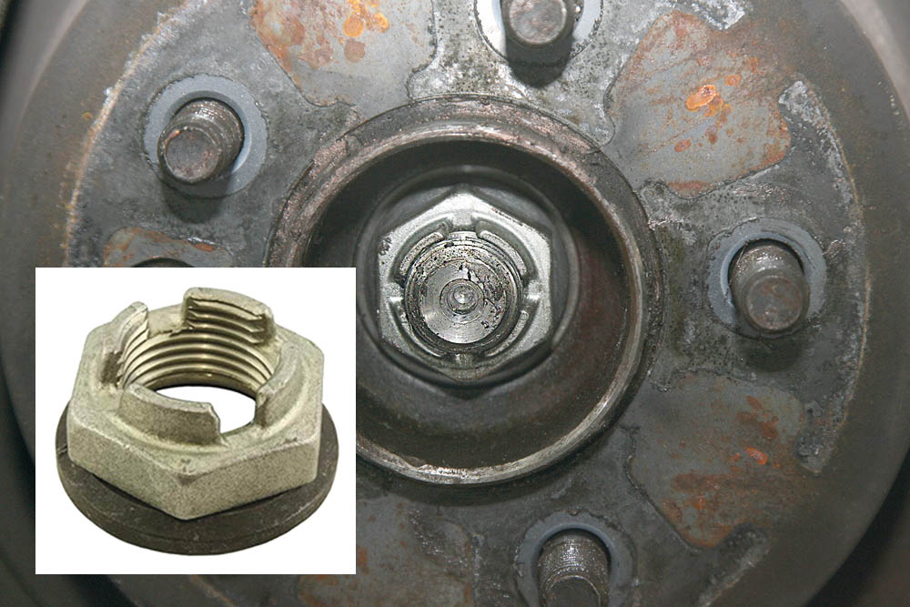
Our hub retaining nuts LR024151, M24 x 2 mm for later shafts don’t need staking. Earlier halfshafts use RFD500020 M24 x 1.5 mm, which will not fit later shafts.
Did you know that you can now get access to the entire archive of Land Rover magazine content with our brand new digital archive? You can enjoy all the issues since the launch of the magazine – use the search bar below to find features, reviews and other great content: