


11 January 2022
|
 Trevor tightens the clutch pressure plate
: credit: © Trevor Cuthbert
Trevor tightens the clutch pressure plate
: credit: © Trevor Cuthbert
With the engine off the chassis, Trevor takes the opportunity to change the clutch, flywheel, crank oil seal and oil pump bolt
NEED TO KNOW:
Time: Around 4 hours
Cost: £596.94
Difficulty: 4 out of 5 stars
Models: Defender 90, 110, 130, Discovery 2
Tools needed: Engine crane, or other suitable lifting gear. General workshop tools. Clutch alignment tool.
Parts & costs: Oil pump sprocket bolt, LYP101400. Britpart £4.74; Sump gasket, LVK500040. Britpart £10.20; Td5 Single Mass Flywheel Bundle. LOF Clutches £582
Work safely:
• Do not move engine crane with engine raised
• Never work or reach under a suspended load
• Wear protective gloves
• Wear safety boots
Contact: LOF Clutches, www.lofclutches.com, Tel 01164 422517
Not every Land Rover that comes in to my workshop for a new chassis has a new clutch fitted. Sometimes the owner will know the clutch is in good condition – perhaps because they had it replaced recently. Others may be keeping a tight rein on the budget, and have the “if it’s not broke, don’t fix it” attitude (possibly false economy with a clutch of unknown mileage). I remember one owner who said at the workshop that his clutch would be okay, only to telephone me on his way home to ask me to change it after all. It was a very good thing he did – when I took it apart, the clutch was worn out and his clutch fork (one of the earlier pressed steel types) was fractured and about to break through.
Changing a clutch is normally a lengthy and costly job, far less so on a vehicle that is partially dismantled for a chassis change (slightly longer for this job because of the tricky rear main oil seal change on the Td5 engine). Here, the owner had decided well in advance that he wanted a new clutch, and had already purchased a complete single mass flywheel conversion kit to be fitted.
Separating the transmission from the engine
It’s a case of unbolting the components, detaching items such as wiring harness and breather tubes, and pulling apart. In practise, these heavy assemblies need lifting gear and a means to support one part of the job while the other is moved away from it. Lifting needs to occur at a precise point and at the correct angle to cleanly separate the parts. Be mindful of your own safety while lifting and handling heavy components.

Still supported: The engine and gearboxes are still suspended from the engine crane after lifting from the rolling chassis. With supports underneath, the LT230 transfer box oil is drained.

Not all of them: A few of the bolts holding the bellhousing of the R380 gearbox to the engine can be removed, including this small flange bolt, using an 8mm spanner.
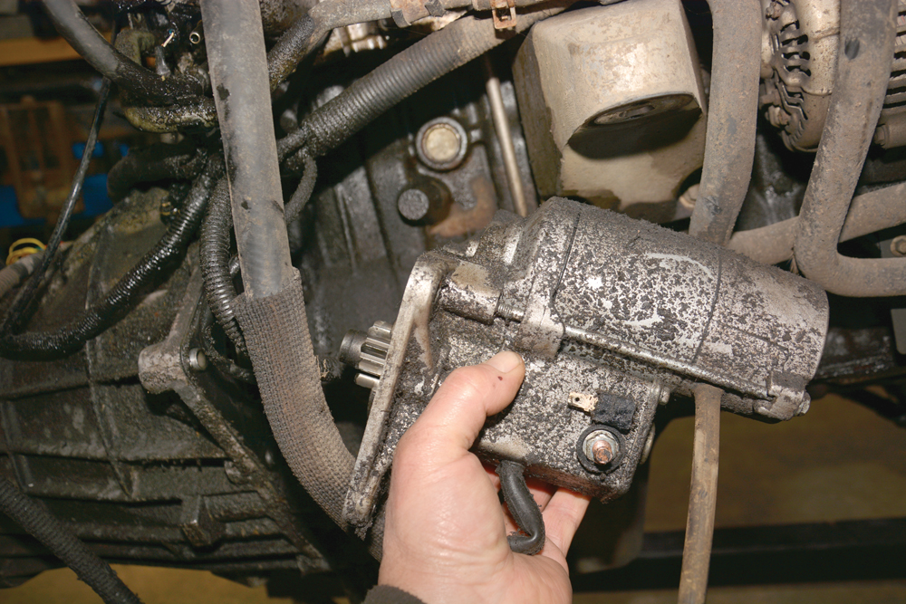
Starter off: The battery cable and smaller spade terminal are disconnected from the starter motor and solenoid. Flange bolts and nut are removed, and the starter withdrawn.
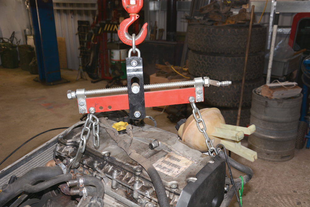
The right tool: The chains that had been lifting the engine and gearboxes are taken off, and an engine leveller is fitted to the engine alone to raise it.

Crack them off: The remaining bellhousing to engine bolts are removed now, and the wiring harness to the gearboxes has been disconnected and draped over the engine.
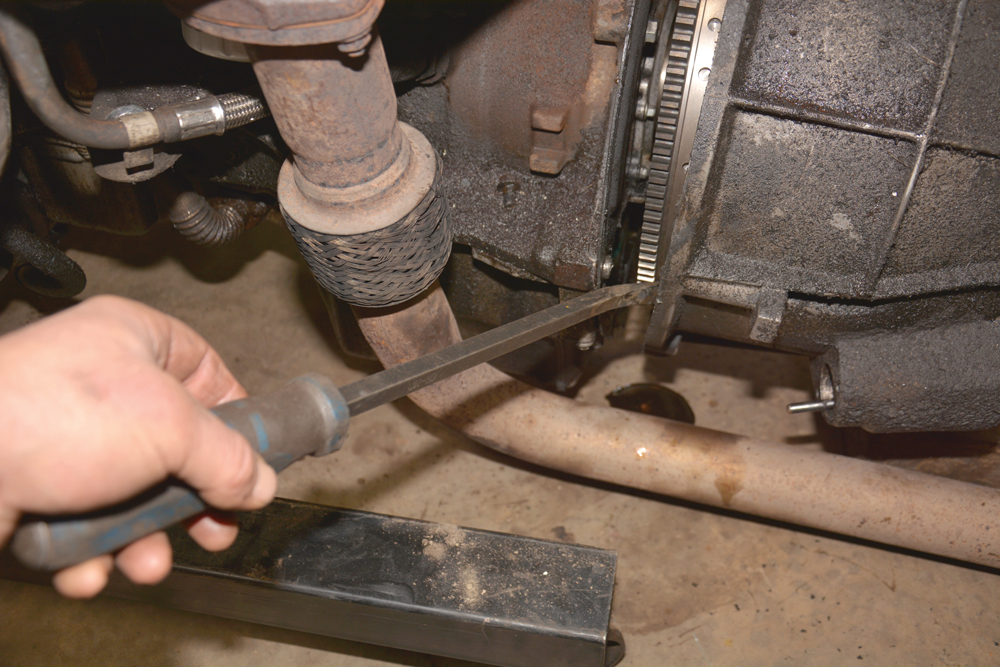
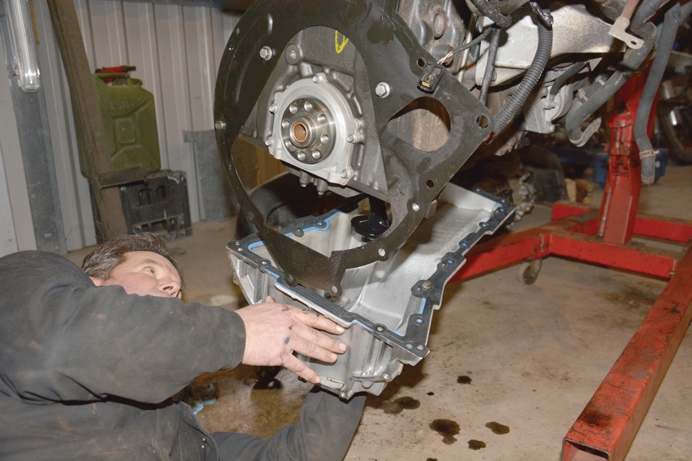
Supported on blocks: The engine and gearbox are now separated using a combination of careful leverage with a pry bar and pulling on the suspended engine to get them apart.
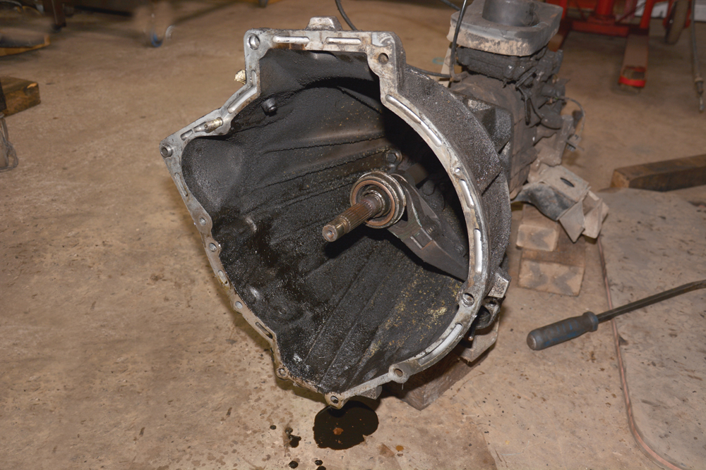
What is the cause? As the engine was separated from the gearbox, a small puddle of black oil formed on the workshop floor, so the cause will have to be investigated.
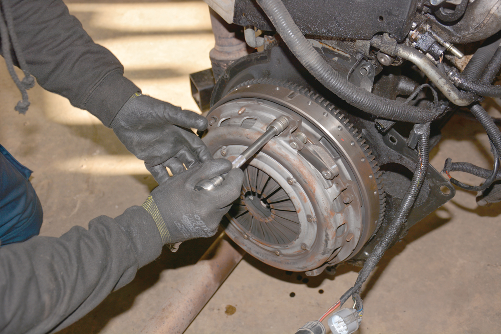
Clutch removal: Now clear of the gearbox, the clutch pressure plate is loosened from the back of the engine (flywheel) by removing the M6 nuts with a 13mm socket wrench.

Well worn: The clutch friction plate’s remaining thickness suggests it’s over half way through its life, so it’s sensible to replace it with a new one at this stage.

Dual Mass Flywheel: There is a fair degree of lateral play in the flywheel, as well as excessive circular play, so the flywheel is removed by taking out the eight bolts.
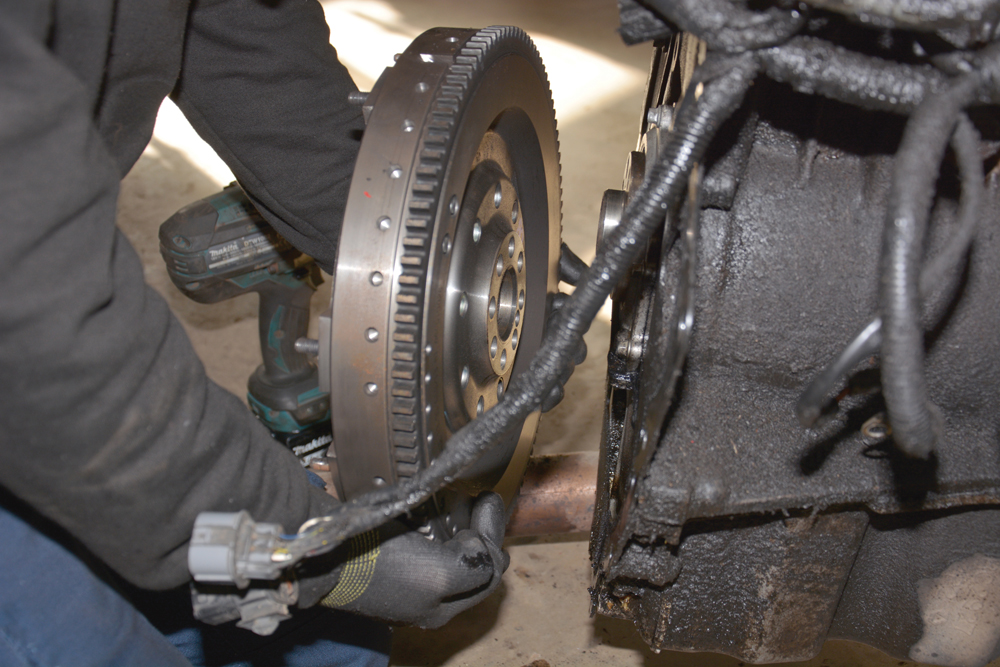
Mind your back: The flywheel is very heavy and awkward to hold, so great care is needed when lifting it off the crankshaft flange at the back of the engine.
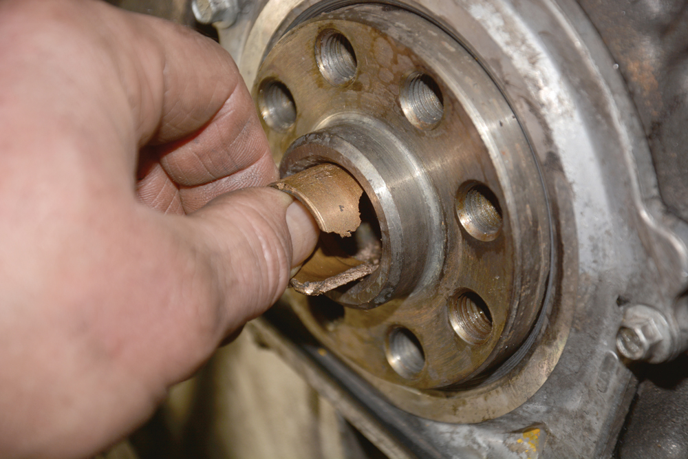
Broken up: The spigot bush (or spigot bearing) was very easily removed by hand as it was quite worn and relatively loose in its recess in the crankshaft.

Gently, carefully: A new spigot bush is tapped squarely and evenly into position using a soft faced hammer/hide mallet to avoid physical damage to the shape of the bush.
Replacing the rear main oil seal and the oil pump sprocket bolt
While the engine is out it’s an ideal time to inspect and replace other parts that can deteriorate, such as the rear main oil seal. There was evidence of oil leaks, possibly from the rear bung on the cylinder head or a failed rocker cover gasket, but the rear main oil seal was chief suspect. Changing this on the Td5 engine is more complicated than, say, the 300Tdi engine, because dowels in the sump gasket locate into the metal part of the oil seal assembly. So the sump needs to be partly lowered (or preferably removed) to replace the sump gasket.
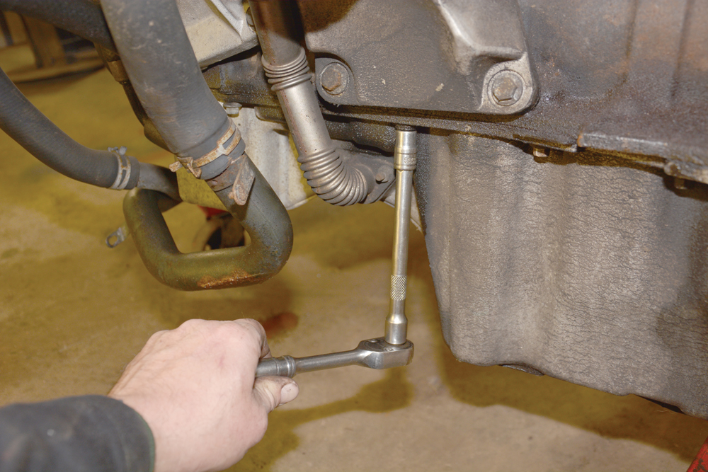
Drain the oil first: The engine sump is held in place by a series of M8 flange bolts, which are loosened and removed using a 10mm socket wrench.
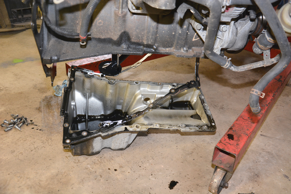
Still oil in there! With all of the bolts removed and the gasket seal broken,
the sump is lowered to the floor, and a good clean up can now begin.
Dowels out of the way: Now that the sump and gasket are out of the way, it is possible to remove the rear main oil seal, using an 8mm socket on the M6 flange bolts.
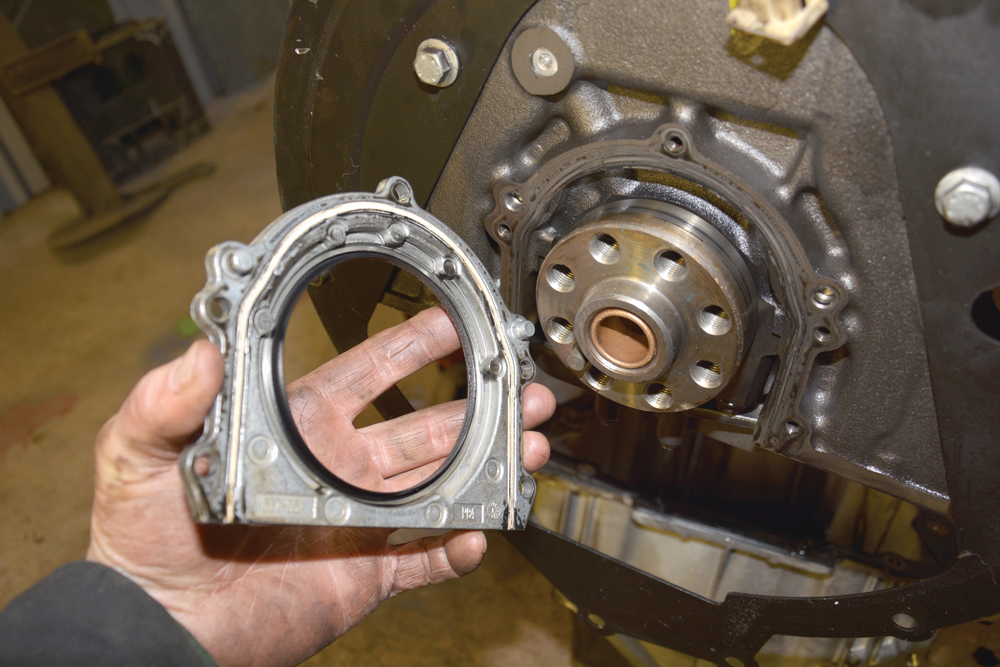
Discarded: The old rear main oil seal has been eased off the crankshaft and will be added to the pile of alloy metals destined for the metal recycling yard.
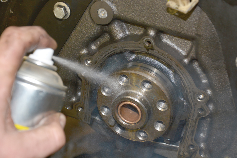
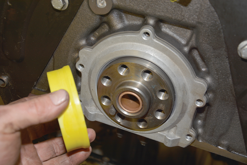
Clean up: The mating faces at the back of the engine and the crankshaft flange are sprayed with brake cleaner and wiped to remove any oil and dirt.
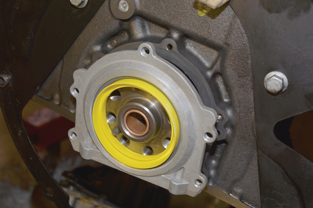
Helpful aid: The new oil seal has a plastic fitting ring in place, which is eased over the flange on the crankshaft, so that the delicate seal is not damaged.
Snaps in place: The new oil seal is pushed evenly into position, keeping it parallel to the mating surface at all times. When the seal is seated, the plastic ring is withdrawn.
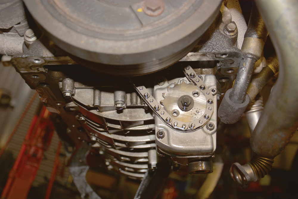
Oil pump bolt: With the sump off, it’s worth replacing the oil pump sprocket bolt, which has been known to come loose, resulting in oil starvation (though this one was secure).
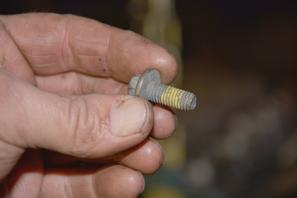
Cheap fix: The new oil pump bolt has thread lock pre-applied, offering peace of mind that catastrophic engine failure will be avoided. Torqued up to 25 Nm (18 lb ft).
Pristine inside: The sump has been thoroughly cleaned inside. A new sump gasket is held in place by a thin bead of gasket seal, making the job easier for one-person refitting.
Fitting the new flywheel and clutch
The owner wanted a single mass flywheel instead of the standard OEM dual mass flywheel which Land Rover researched, designed and engineered: the single mass has no moving parts to fail, but doesn’t damp out the engine vibrations to the extent of the dual mass. The method of fitting both types of flywheel and differing clutches is similar. I fitted an LOF clutch package containing everything needed, including a syringe of lubricant for the spigot bush and input shaft. The owner supplied a replacement single mass flywheel and corresponding clutch, which came with a set of special fixing bolts.
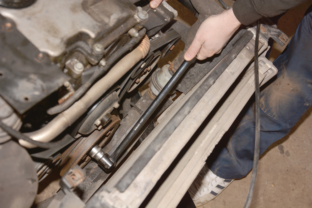
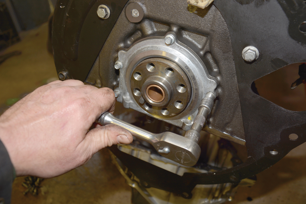
Hold it firm: A 24mm socket on a long breaker bar is used to prevent the crankshaft from turning at the front of the engine, held by an assistant.

Torque procedure: The special bolts, provided in the kit for the single mass flywheel, are tightened evenly to 40 Nm and each are subsequently turned by a further 90 degrees.
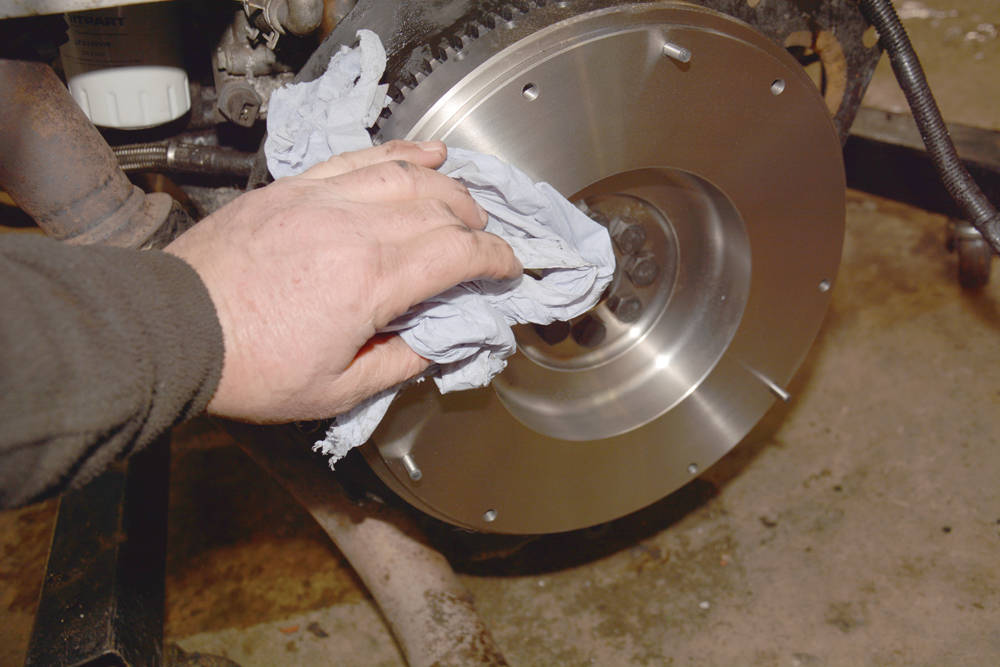
Degrease: The surface of the flywheel must be cleaned of all oil and grease to avoid contamination of the clutch plate friction material.

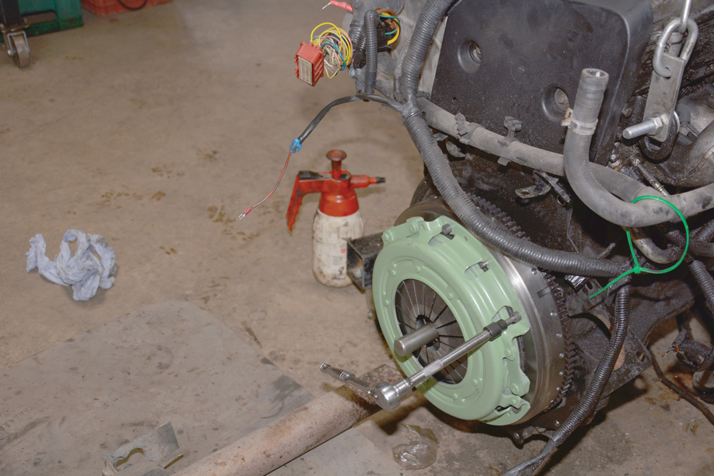
Correct way around: The clutch plate (driven plate) is aligned concentrically, sliding it over a length of old gearbox input shaft entered in the spigot bush as the perfect alignment tool.
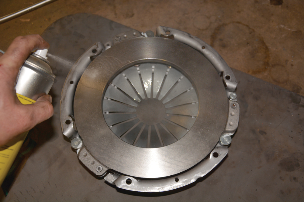
More cleaning: Just as the flywheel was degreased, it’s equally important to clean the surface of the clutch pressure plate using brake cleaner fluid, to avoid any chance of slippage.
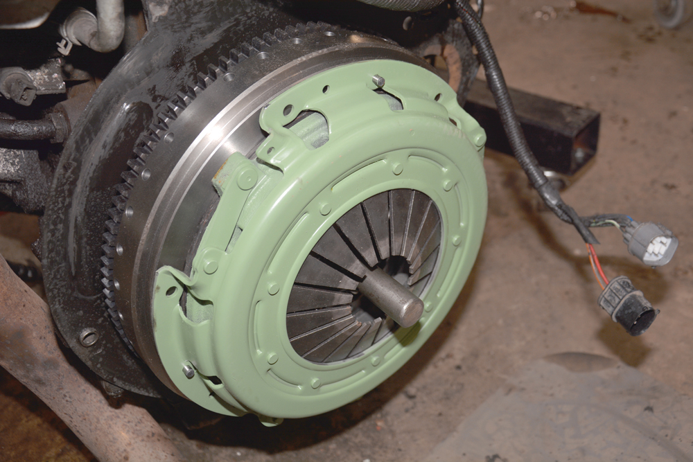
Locating posts: The clutch pressure plate is now offered up to the flywheel and fitted over the three dowels protruding around the outer edge, thus aligning it perfectly.
Thread locked securing bolts: Six socket head bolts (supplied) are tightened gradually and evenly around the circumference, a little at a time, to tighten the pressure plate evenly onto the flywheel.

On Td5 models: The old clutch fork is removed by releasing this clamp, held by an M6 screw loosened using an 8mm ratchet spanner, and withdrawn along with the release bearing.
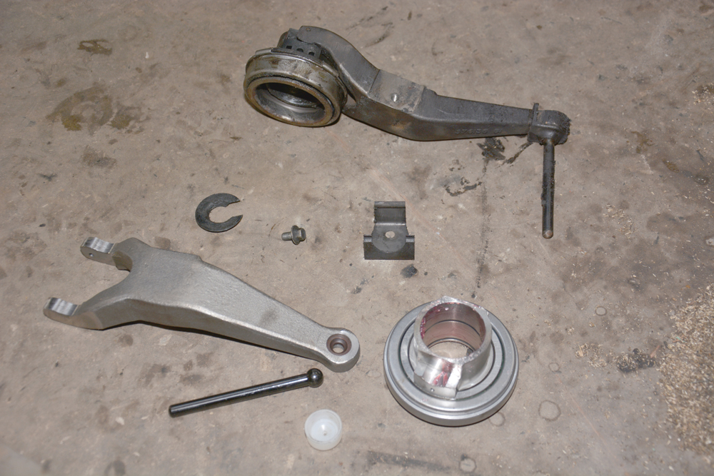
Quite worn: A new clutch fork is needed in this case, as well as the operating rod and nylon bushing. The release bearing is generally replaced as a matter of course.

All ready now: The new clutch operating mechanism is now in place within the bell housing. After final checks, the engine and gearboxes can go back together.
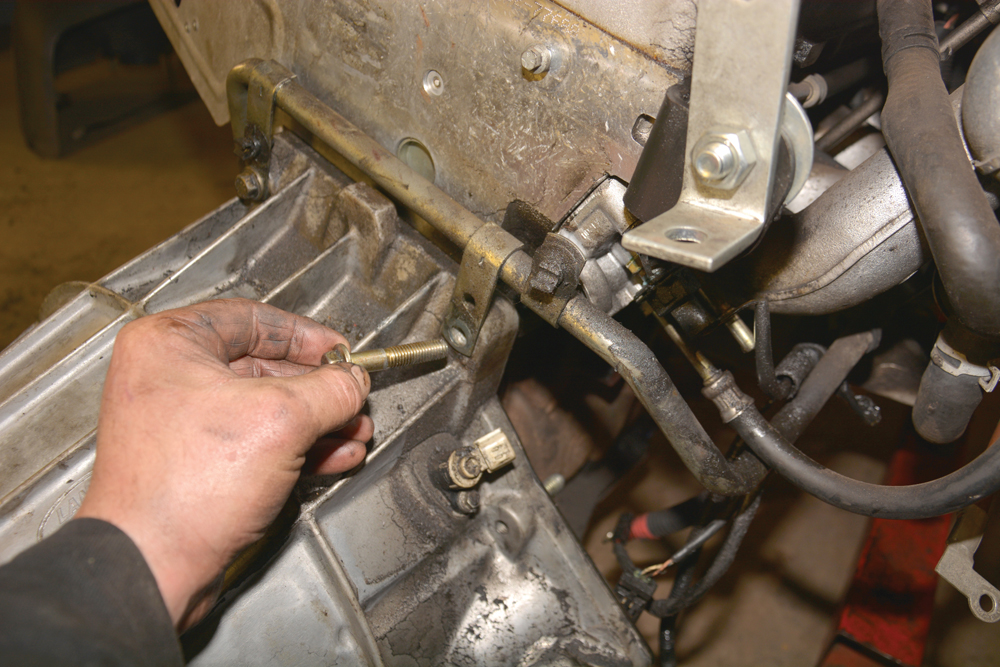
Tighten gradually and evenly: Take care when mating the engine and gearbox to ensure nothing is trapped between them; this bracket was not originally fitted correctly, but is now in the right position.
Find more great technical advice from our experts here.
Budget Digital Subscription
Get access to over 7 years of Land Rover Monthly – that’s almost 100 issues plus the latest digital issue. The issues are fully searchable so you can easily find what you are looking for and what’s more it’s less than 10p a day to subscribe. Click here and start enjoying all the benefits now.