


01 September 2018
|
 : credit: © JLR
Suspension bushes deteriorate gradually, so the performance improvement from renewing them can be surprising. Mark Williams gets his Freelander 1 re-bushed
Model: Freelander 1
Time: 7 hours
Cost: £438.82
Difficulty: 3/5 stars
Tools needed: General workshop tools, torque wrench, hydraulic press or bush removal kit (optional).
Contact: Bishops 4x4, 15 Imperial Way, Peterborough PE7 3GP. Tel: 01733 242888, bishops4x4.co.uk. Bushes from powerflex.co.uk
Work safely: Wear face and eye protection when using a hydraulic press, taking care to ensure components and tools are stable during the pressing out process.
The Freelander 1 is now one of the cheapest Land Rovers on the secondhand market, with MoT-able examples as low as £500 and a mint, late Td4 as little as £2500. Although the Freelander – cheerfully named the Hippo by enthusiasts – was never a serious off-road tool, even die-hard mud pluggers occasionally end a tough greenlane drive scratching their heads and wondering how the Hippo came through unscathed. The fact is, the only failing in the off-road department is the low ride height, but for everything else, its four-wheel drive and electronic traction control get the Hippo out of all but the tightest spots.
My 2005 Td4 HSE manual Freelander is heading, inexorably, for a life of light off-roading, the general idea being to modify the car sufficiently to cope with a few greenlaning days without making it undriveable on the road. To be honest, I’d never had any concerns about the suspension, but when some rare workshop time at Bishops 4x4 became available, I bought a full set of Powerflex polyurethane bushes to be fitted on the front and back, and took the plunge.
The original bushes are bonded rubber items, notoriously difficult to remove, while the PU replacements are easy to fit and to replace, and they’re so durable it is doubtful they will ever be replaced in the lifetime of this car. In addition to the new bushes, it’s also important to have new replacements for all the bolts and washers removed in this procedure. I’ll report back on the effect on the ride in a later feature in Writers’ Rovers.
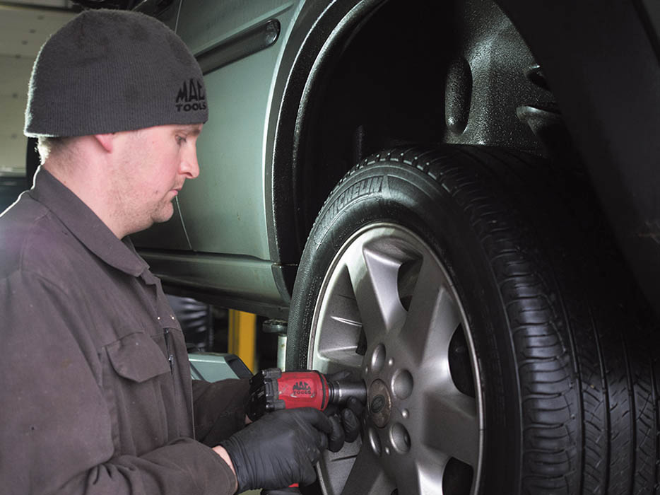
If not using a ramp, chock the front wheels and jack the car, supporting it on axle stands. We started at the back.

As they are exposed to road salt and water throughout their life, all the bolts are potentially seized, so if you have to opportunity, give them all a shot of penetrating oil ahead of time.
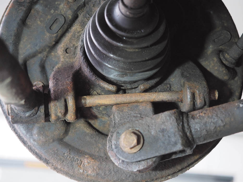
The bolts securing both link arms to the hub carrier are particularly prone to seizure. Right-hand bolt came free, but the left was seized (see later).
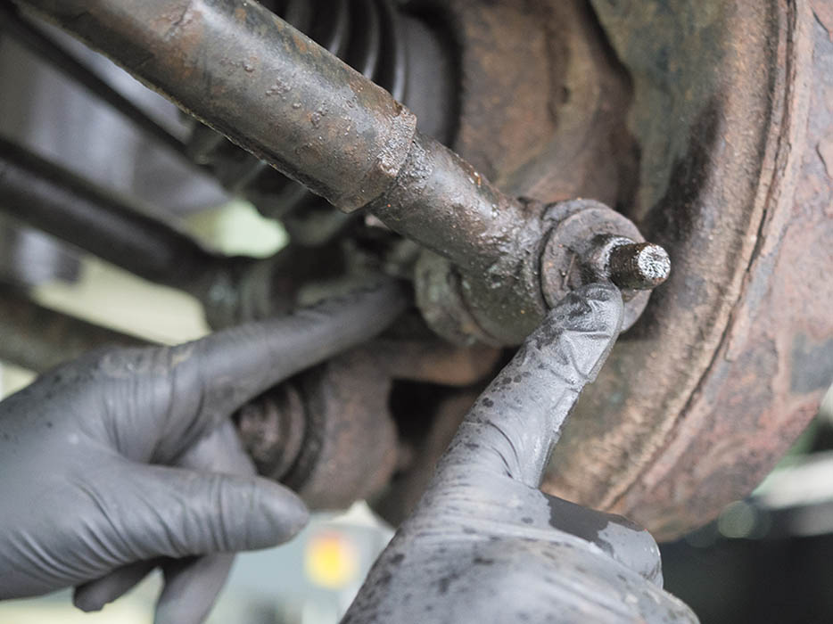
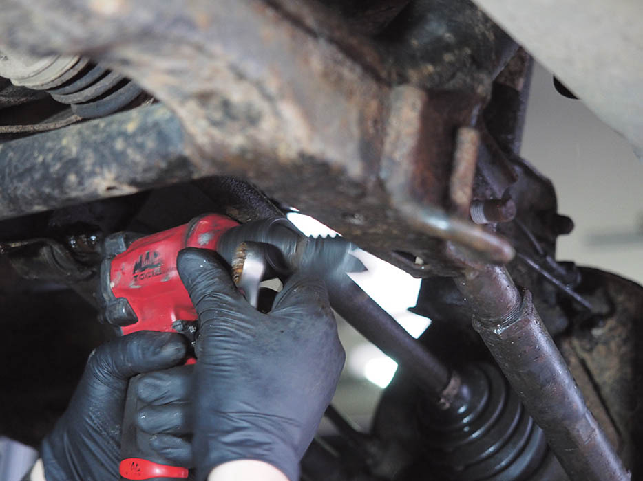
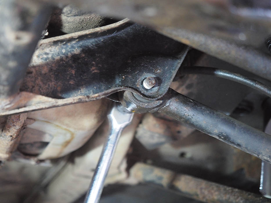
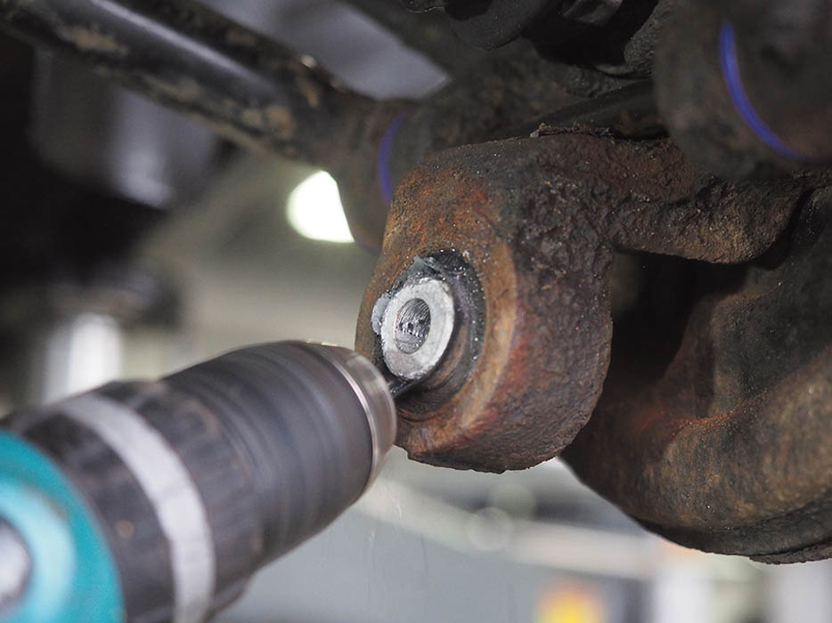
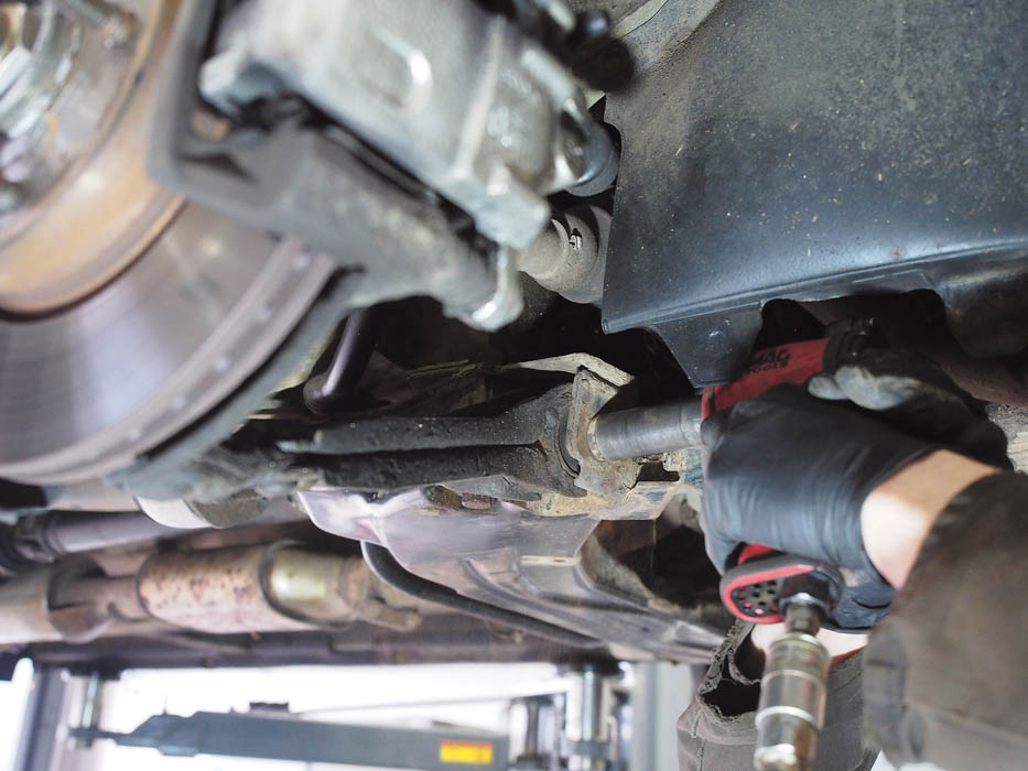
Remove the single nut at the rear end of the hub carrier bolt, which secures the suspension’s adjustable transverse link.
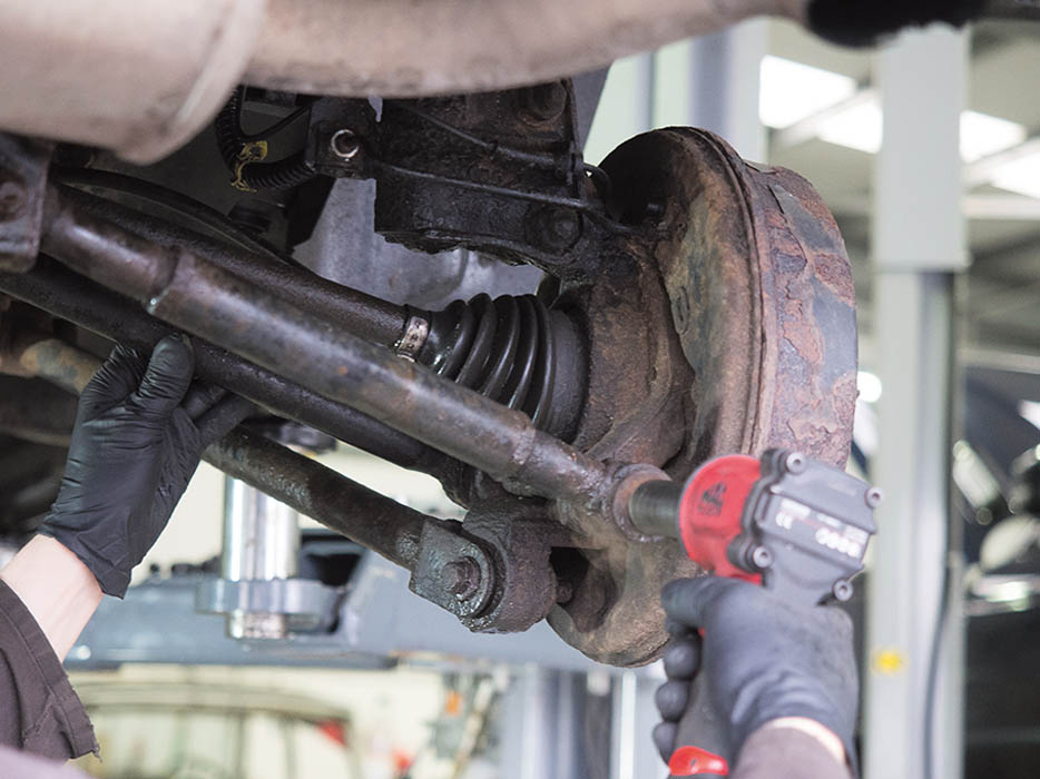
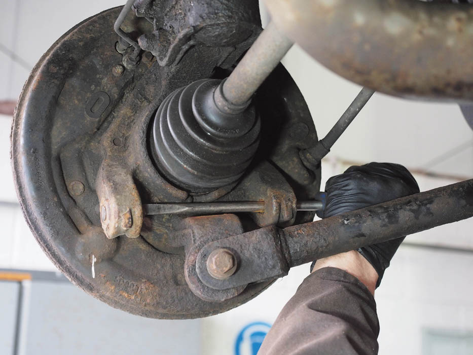
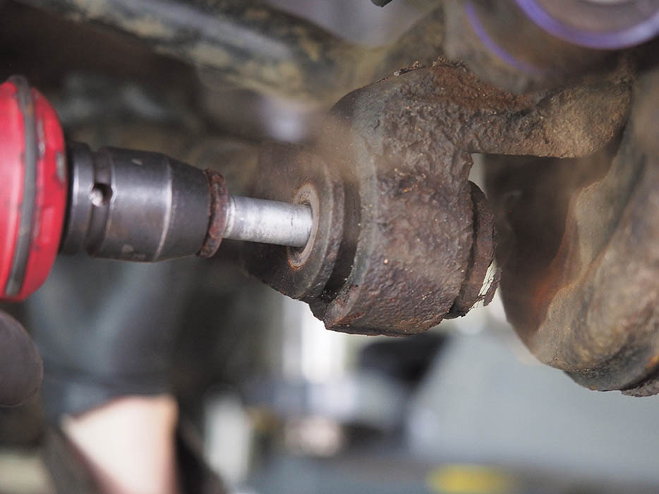
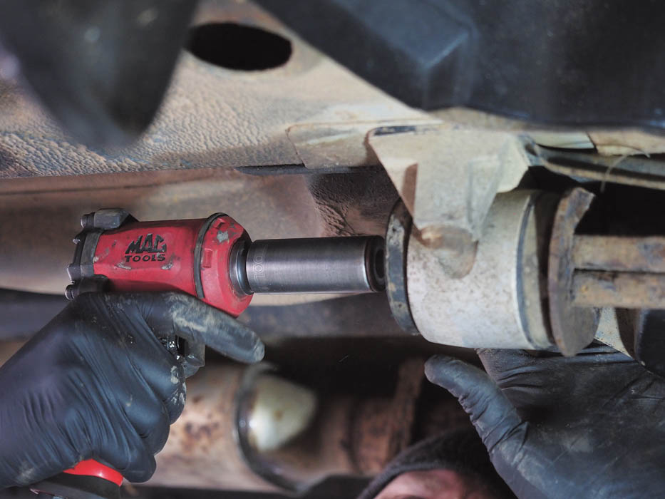
The bolt passes through the hub from the front end. It may well require significant force to turn it to facilitate removal.

Using a drift, as we have done, drive the bolt through the hub carrier until the threaded portion is inside the bush.
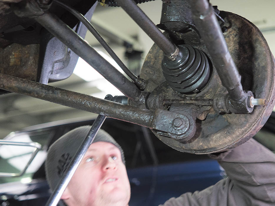
Now remove the bolt securing the adjustable transverse link to the subframe, lift the link clear and slide it off the hub carrier bolt.
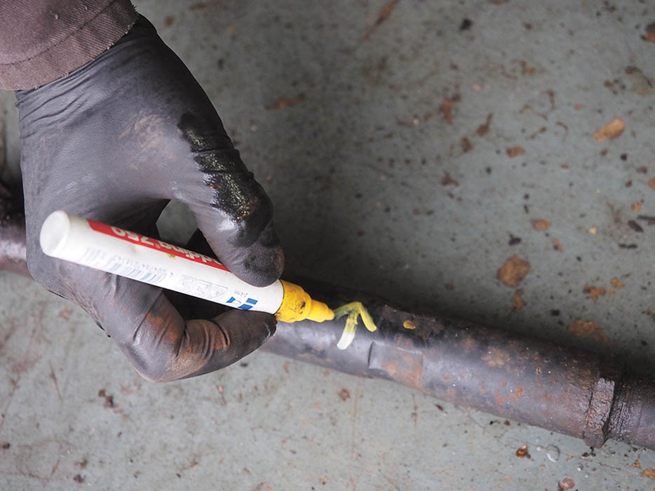
Mark the adjustable link in a bright colour (and the front link) with an arrow to remind you later of its orientation when refitting.

The hub carrier bolt is driven out (while holding the other link in position), taking care not to expand the end and jam it.
Our left side hub carrier bolt was so seized that it sheared off at both ends after attempting to remove the nut and turning the head.
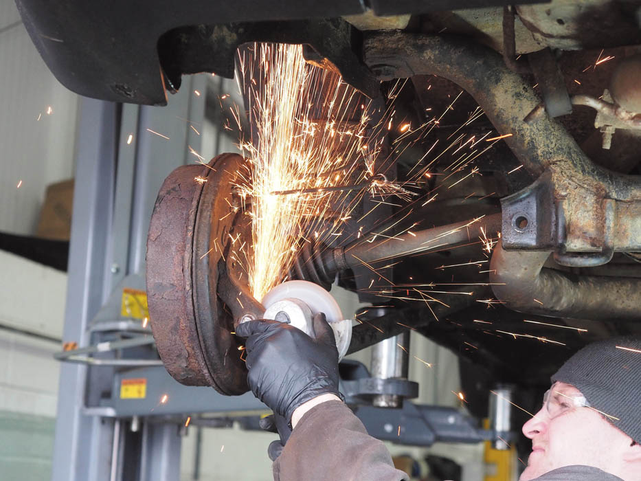
With both links detached, we used an angle grinder to cut out the visible centre section of the bolt, between the bush mounting points.
The remaining, un-threaded pieces of the bolt were then drifted out. Detaching the trailing arm from the hub carrier helps here.
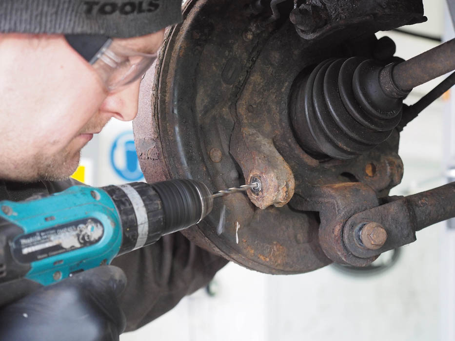
But this piece of bolt still refused to budge, so we had to drill it out. The heat generated by drilling will often dislodge the remaining piece.
At this stage, it may help to remove the subframe bolt securing the transverse link, to help it clear the trailing link, which we will leave in place for now.
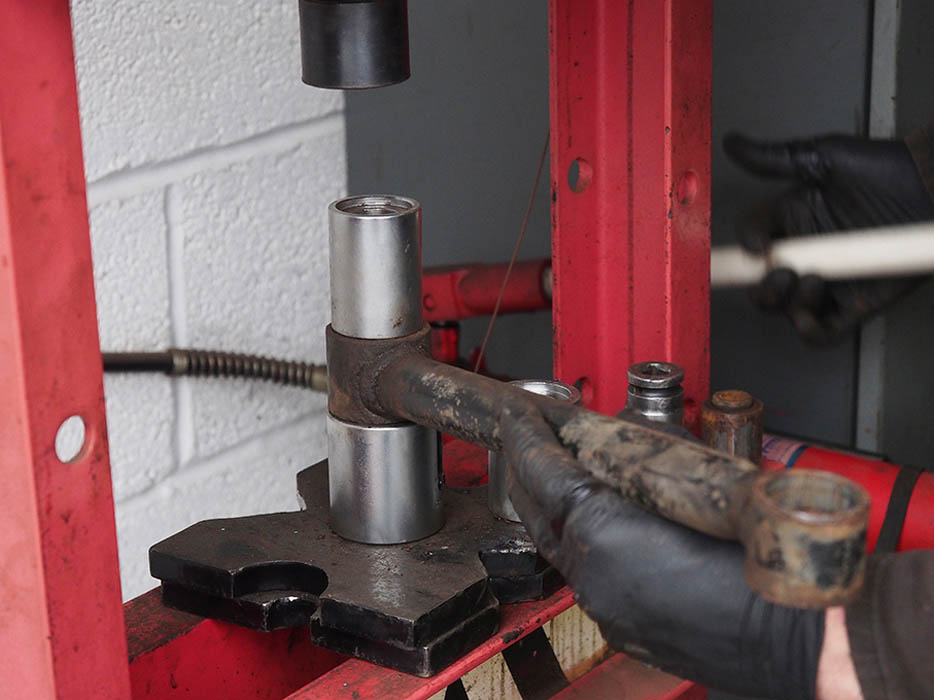
A bush removal kit and a hydraulic press is used to extract the bushes from the suspension components.
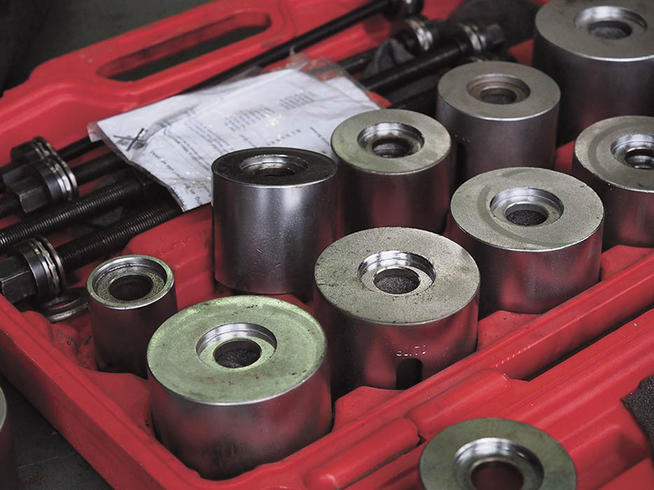
A selection of dies and mandrills is usually needed to ensure the bush is pressed out without damaging the housing.
As this trailing link bolt comes out, you can see there is not enough clearance behind the bush to use the bush removal tool.
First drill out the rubber of the bush progressively. A sharp, new reaming bit will make this job easier and more efficient.
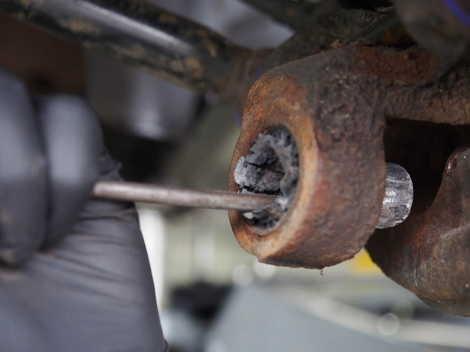
Once the rubber has been partly cut away around, the steel inner section of the bush can now be drifted out as pictured.
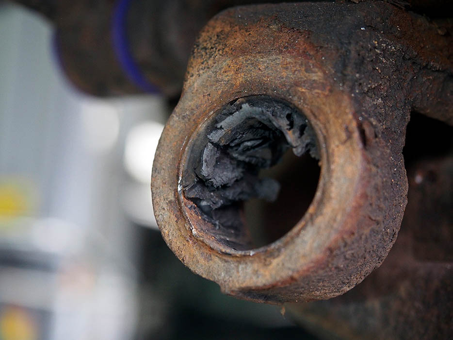
Using pliers, part of the remaining rubber can be pulled out to reveal the steel outer bush casing inside the hub carrier bore.
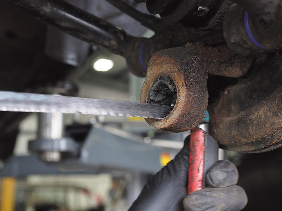
A hacksaw blade is passed through the hole and the saw frame refitted to the blade so we can carefully saw through the bush outer casing.
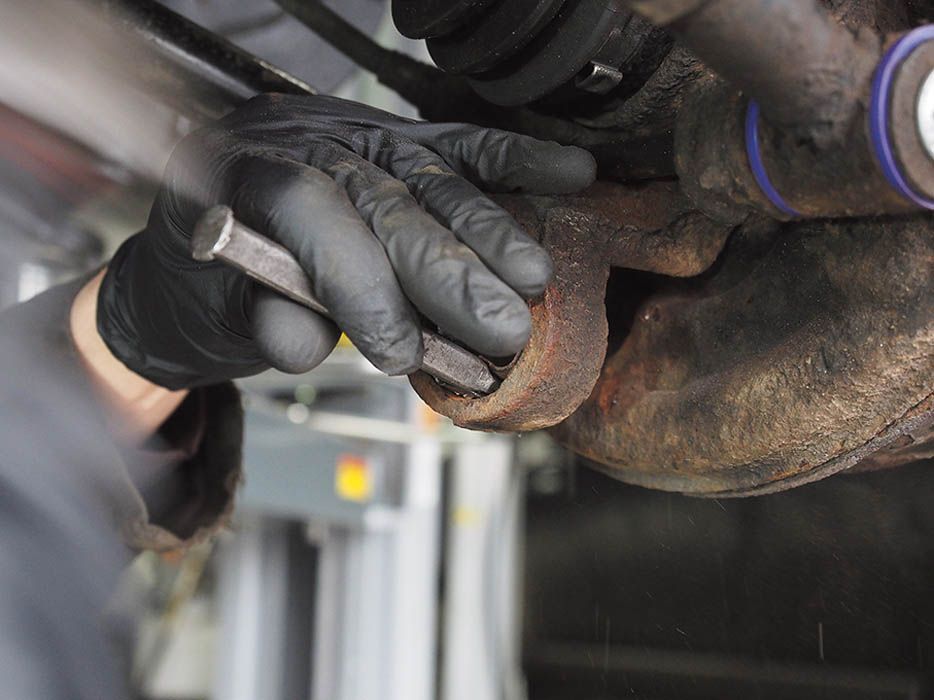
We then use a chisel to begin peeling the bush casing clear of the hub carrier and eventually drift the loosened casing out of the hub.
When any bush casing is removed, rub down the inner faces before fitting a replacement
The Powerflex bushes are in two halves with a steel inner (no outer casing). Bores are cleaned smooth with emery before re-bushing.
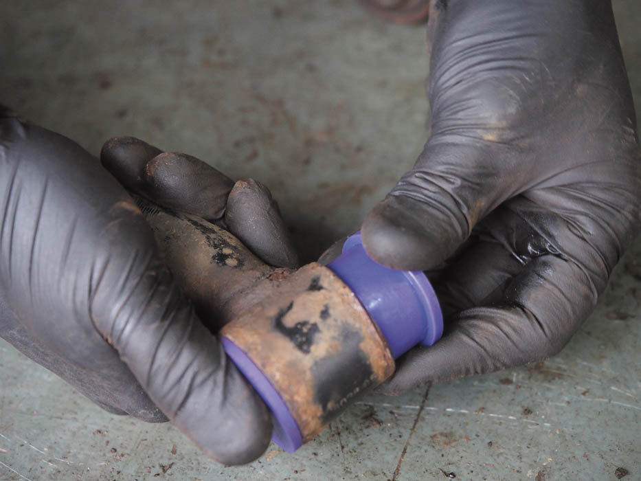
The new bush halves are simply pushed into the link and the steel inner smeared with the supplied silicon grease and tapped through them.
All bolts should be replaced with new to refit the link arms. The bolts are nipped up but not torqued at this stage.
Front suspension bushes
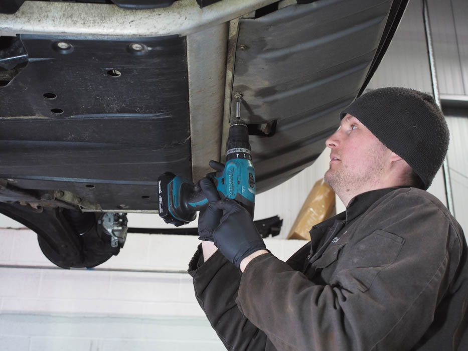
To access the front lower arms this front valance is first removed – four screws to the brackets and the four to the wheel arch.
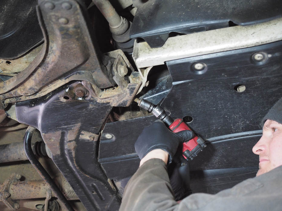
The engine undertray is removed after releasing two 10 mm bolts securing the rear and the four 13 mm bolts either side.
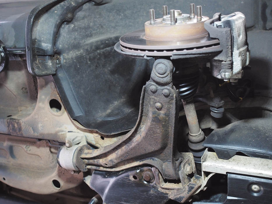
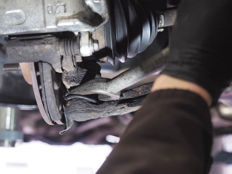
The front lower arm assemblies each have two bushes on the inboard sides, one front and one rear in an aluminium housing.
The first job is to remove the nut and bolt securing the lower arm bush at the front, which should come away fairly easily.
The rear spigot of the lower arm passes through the aluminium housing and its bush and is held by a single nut, being removed here.
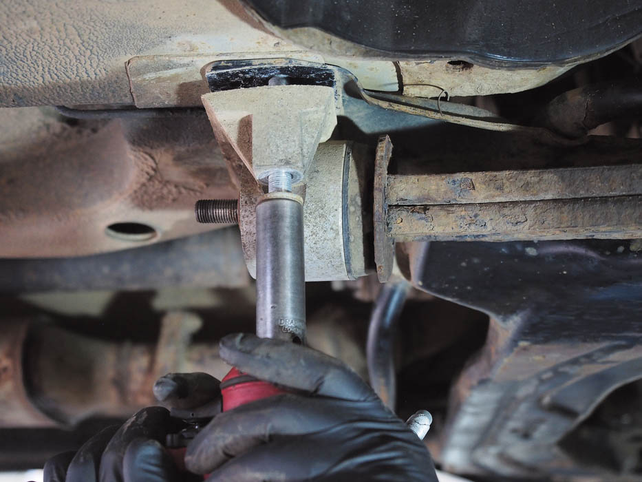
The aluminium housing is still held to the underbody by two vertical bolts. Removing these will release the housing.
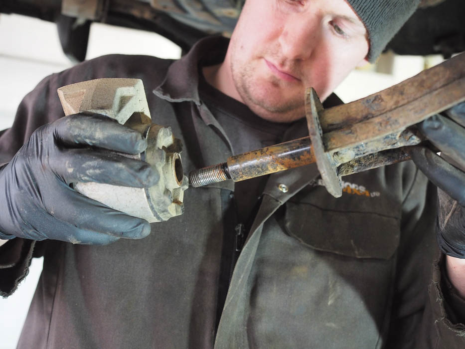
The bush assembly should then simply slide off the lower arm’s spigot with minimal persuasion, leaving the arm still attached to the vehicle.
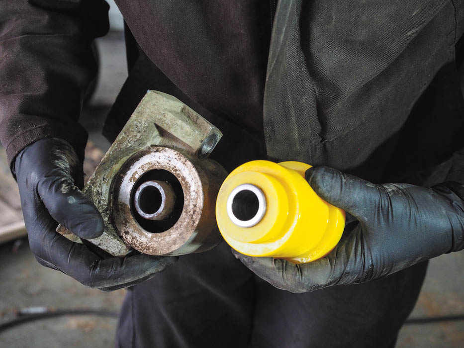
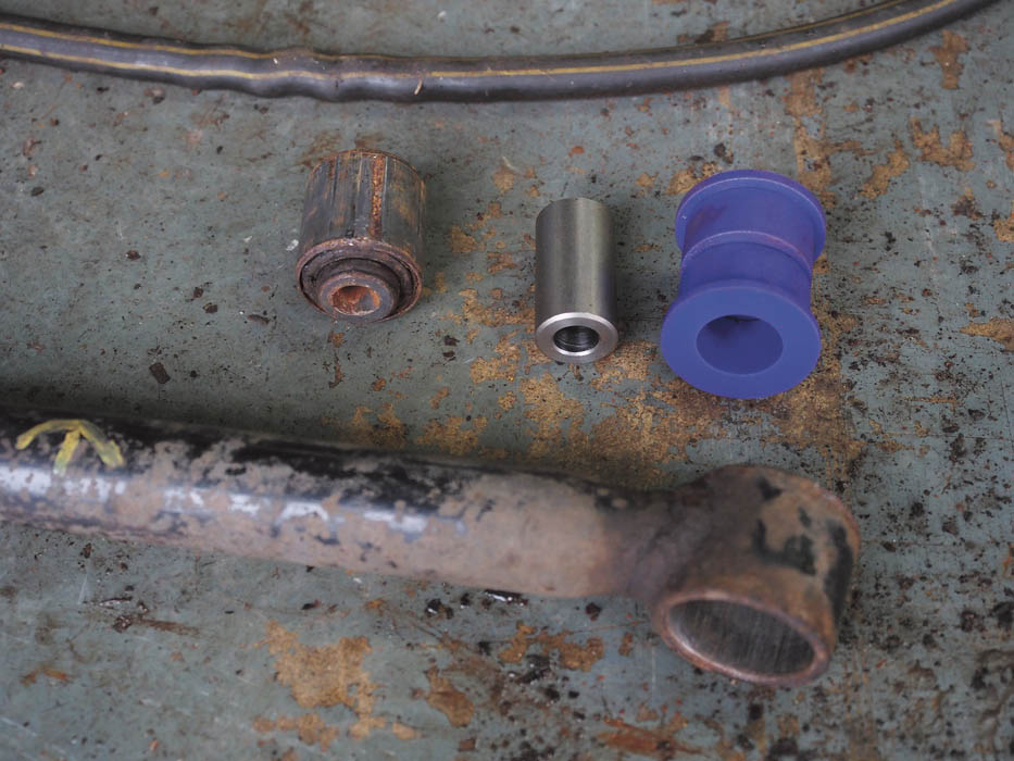
The original bush (left) must be drilled or pressed from its housing using the methods we saw earlier before fitting the new bush (right).
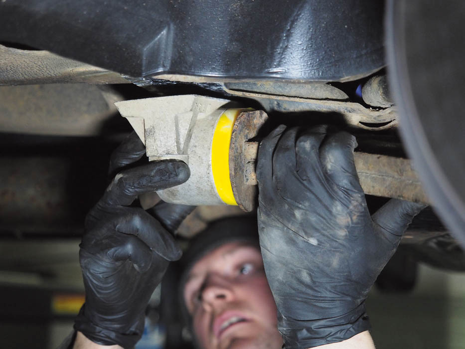
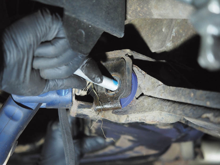
Having fitted the new PU bush into the alloy housing, the assembly can be slid on to the lower arm and offered up to the mounting points.
At this stage, we replace the bush’s rear washer and nut, but we don’t tighten to torque just yet. We’ve renewed both housing bolts.
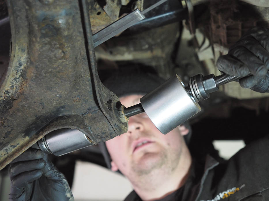
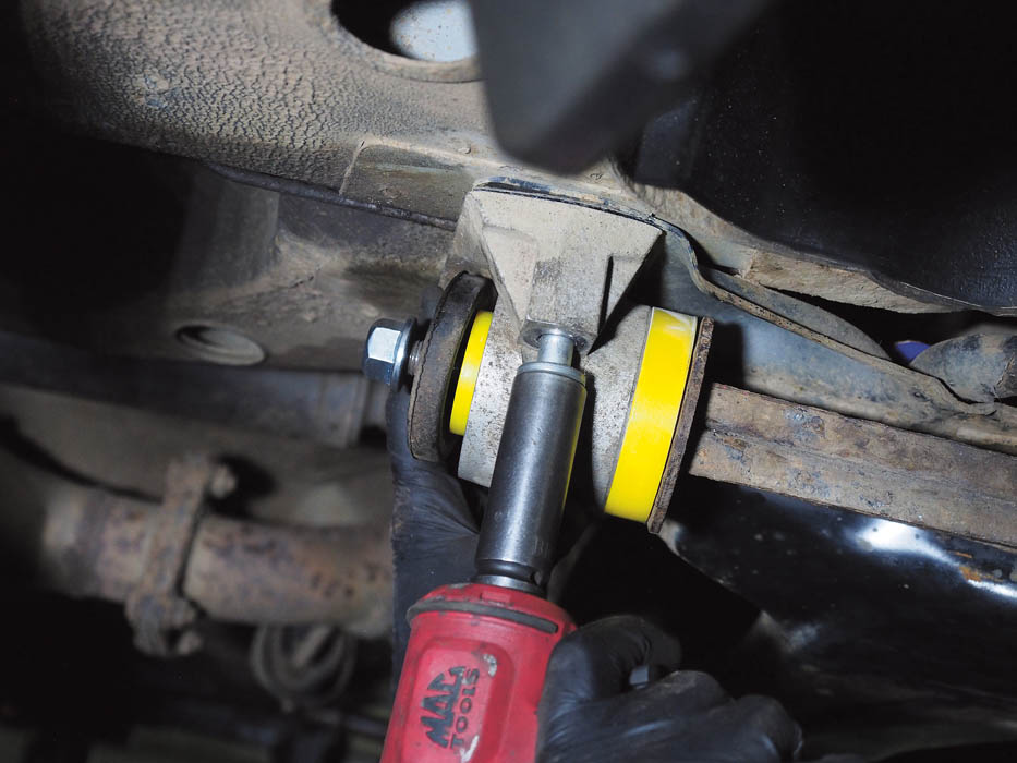
To remove the front bush from the lower arm we’re using a bush removal kit – pulling it through by winding a nut down the stud thread.
You should not normally need to remove the lower arm, but if you do, it needs to be separated from the hub using a ball joint splitter.
Now the front lower arm bushes are replaced with the new Powerflex items in the same way as the rears, using new bolts again.
Front anti-roll bar bushes
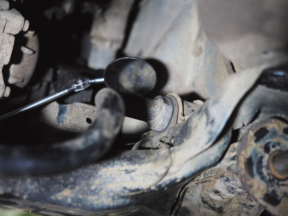
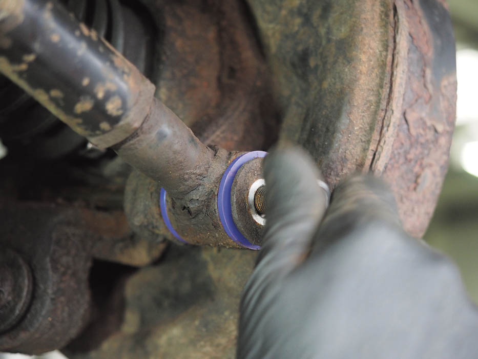
The anti-roll bar has two bushes, each held under a U-shaped bracket. A mirror can be handy to ascertain the bolt condition and size.
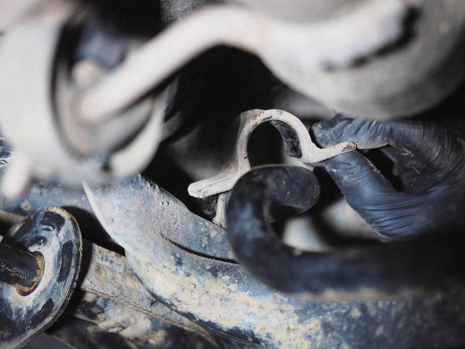
With the bracket prised up and lifted off, the bushes are easily worked off the anti-roll bar and removed ready for replacement.
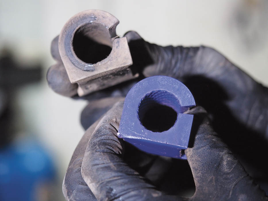
The original and replacement bushes, which you can see are split on one side for removal and replacement without removing the anti-roll bar.
Final tightening
With all bushes now replaced, they must be torque-tightened, with the weight of the vehicle on the suspension.
Anti-roll bar saddle clamps 23 Nm 17 lb-ft
Lower arm front bush to subframe 190 Nm 140 lb-ft
Lower arm rear bush housing to body 105 Nm 77 lb-ft
Rear bush housing nut 140 Nm 103 lb-ft
Trailing link to rear hub 120 Nm 89 lb-ft
Transverse link 120 Nm 89 lb-ft
Transverse link to body 105 Nm 77 lb-ft
Budget Digital Subscription
Get access to over 7 years of Land Rover Monthly – that’s almost 100 issues plus the latest digital issue. The issues are fully searchable so you can easily find what you are looking for and what’s more it’s less than 10p a day to subscribe. Click here and start enjoying all the benefits now