


21 July 2021
|

Towing equipment can be retro-fitted to a Discovery Sport. Dave Barker shows what’s involved
Time: 3 hours
Cost: See below
Difficulty: 3/5 stars
Model: Discovery Sport
Tools: General workshop tools: including 4 mm Allen key; T25 Torx socket bit; 10, 19, 22 mm spanners and sockets; torque wrench plus angle torque gauge.
Parts & Costs: Tow kit bar, PLCT0142LR, Discovery Sport (7 seats with spare wheel), from £198 to £602, Britpart; 13-pin tow bar electrics, VPLCT0244, Discovery Sport (7 seats with spare wheel), from £78 to £110.
Work safely: When planning to work underneath a vehicle on a lift/ramp, first ensure the equipment is rated to lift the weight of the vehicle and is serviceable.
• Ensure the vehicle is securely supported before you start working.
• Wear protective gloves or barrier cream to protect the skin from oils and sharp edges of components.
• Be aware the tow bar kit weighs a hefty 50 kg.
Contact: Maddison 4x4, maddison4x4.com, Tel: 01845 587407
Adding a retro-fit tow hitch to the Discovery Sport requires the rear body structural impact beam armature (crossmember) to be replaced by a new towbar impact beam armature which supports the tow hitch mountings and uses the same body mounting points. The centre section of the rear valance is replaced with a new section supplied with the kit we’re using, which covers the fixed bolt-on tow bar mounting. A small section of the rear bumper needs to be cut to allow for the towbar, and the cut lines are pre-marked on the inside of the bumper.
Then it’s a matter of installing your chosen electrics – usually the now standard 13-pin socket shown here. Land Rover and some aftermarket electrical kits have a multi-plug that connects directly to the vehicle’s wiring loom. Always check you are buying the correct kit because there are several versions, depending on the configuration
of your vehicle: 5 seats, 7 seats, with or without spare wheel, etc. Our vehicle is a 2015 model year Discovery Sport, 7 seater with spare wheel.
The hardest job on this bolt-on installation is removing the rear bumper, especially if you are not sure about unclipping body fixings. The instructions (accessed on Land Rover’s accessories website) are not great on detail, so study them carefully. They suggest the original impact beam armature, mountings and bumper centre can be discarded. However, if you plan to sell the Discovery Sport in the future and wish to keep the tow bar for another car, you will want to keep all the parts for refitting.
Removing the rear bumper panel

1. Check, double check: It’s important to order the correct tow bar kit for the specific vehicle, double checking the parts and diagram against the car before starting the job.

2. Cover panel: The rear bumper centre cover needs to be removed first. This is secured at the bottom edge by two screws, and along the top edge by eight clips

3. Uncovered: In order to remove the rear side lights, the rear cargo area side panels on each side of the interior need to be removed. They just prise out.

4. Unscrew: We can now access and remove this long spring loaded screw in the side of each rear wing, which secures the rear lights into the bodywork.

5. Lights out: The rear tail light assemblies can now be unhooked and pulled partly out of the bodywork, before disconnecting the wiring multi-plugs to remove them.

6. Bumper screws: Two securing screws in the corners of the rear bumper that hold the lower edges of the bumper assembly to the vehicle body are removed.

7. And bolts: The four bolts that are securing the main section of the rear bumper assembly to the vehicle are now removed. These are the main fixings.

8. Wheel arch: The wheel arch trim is next to be unclipped, then three screws on each side securing the bumper assembly sides to the body can be removed.

9. Maybe hidden: One screw on each side is located on the bottom edge of the bumper assembly. If mud flaps are fitted, the screws may be hidden behind them.
10. Last two: There are two additional plastic plug-type screw fixings which need to be removed from each lower corner of the bumper.

11. Off with the bumper: The bumper assembly can now be carefully worked out and released from the vehicle, remembering to disconnect the parking sensors harness multi-plug (inset pic).
Old armature beam off

12. Armature exposed: Exhaust silencers are supported to the beam by rubber mounts on each side. They are pried off from their mounting brackets and the silencers lowered.

13. Unbolting:The rear impact beam armature is held in position to the body by these three securing bolts on each side, which can now be removed.

14. Lift off: Once all three securing bolts on each side have been removed, the rear impact beam armature is then lifted off from the body.
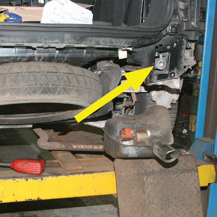
15. Towing eye mount: The recovery towing eye mount is in the right hand body recess. Two bolts, fitted from underneath, are removed and the mount is pulled out of the body.
Installing the new beam assembly

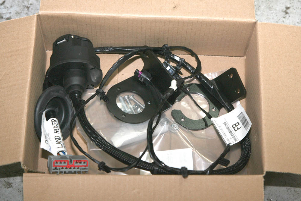
16. In the box: New towing structure comprises a left and right hand support bracket (bottom), new armature beam (middle), hitch and fixings, and new bumper centre panel (top).

17. Plate needed: We’ll be fitting two tow bar mounting brackets into the body. Before the right hand bracket is fitted, this small threaded plate washer is located behind the body.

18. Fit and tighten: The plate needs to be carefully located in the correct position behind the body before fitting and tightening this single holding screw.

19. Mounting bracket: The right hand side tow bar beam mounting bracket is now pushed fully inside the body recess and located into position, aligning the bolt holes.

20. Held in place: Once the mounting bracket is in position, it is then secured with three M12x50 bolts and spacers. The bolts are left finger tight for now.

21. Bolting from under: Working from the underside of the body, four M14x125 bolts are fitted through the body into the mounting bracket, and again just finger tight.

22. Fit in position: Next, the left hand side mounting bracket is positioned into the body recess and secured with the same number of fixing bolts, spacers and washers, all finger tight.

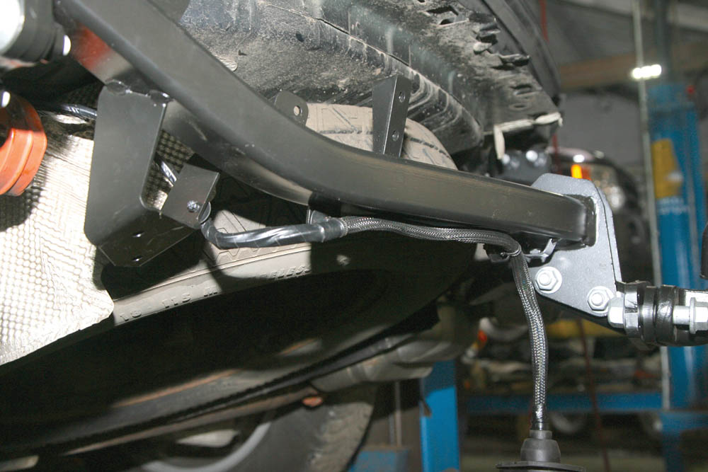
23. Fitting the main beam: The new beam can now be lifted into position, locating it in the two side mounting brackets, and securing it with four M14x55 bolts and spacers each side.

24. Torqued up: After checking the towbar beam is correctly in position the four securing bolts at each side are fully tightened to 110
Nm, then tightened a further 120º degrees.

25. Fully tighten: The bolts securing the mounting brackets to the body are now tightened: three M12x50 to 80 Nm plus 60º degrees, lower M14x125 bolts to 100 Nm plus 240º degrees.

26. Refit exhaust: With the new rear tow bar beam now fully in position, the two exhaust silencers’ rubber hangers are refitted onto the new brackets on the beam.

27. Fitting the neck: The towbar neck is next to be fitted. This locates into its mounting point on the tow bar beam and is secured by two M12x70 bolts, torqued to 100 Nm.

28. The hitch: Next, the tow ball is fitted onto the tow bar neck assembly and secured with two M16x40 bolts which are tightened to 260 Nm torque.
Connecting the electrical system
29. Wiring kit: The new harness is pre-wired to the electrical tow socket and is fitted with a body grommet and multi-plug. Socket mountings and fixings are also supplied.

30. Locate the grommet: With the load bay trim and the tool tray removed, this rubber grommet located in the floor is removed to allow the towbar electrics into the boot area.

31. Feed up and connect: The towing wiring is fed up through the hole with its attached new grommet located into the hole, then the multi-plug is connected to the vehicle’s wiring loom.
32. Clip in place: The towing harness is now clipped up securely onto the cable brackets on the towbar beam where it will be clear of the rear bumper when it is refitted.

33. Secure in place: The mounting bracket for the towing electrics 13-pin socket is bolted into position on the towbar neck, and the electrical socket is bolted to it.
Finishing off

34. Pre-marked cut lines: Before refitting the bumper, a section is cut out to clear the new structure. The instructions show where to cut, and the cut lines are already inside the bumper.

35. Refit the bumper: The rear bumper assembly is now ready to refit using the original fixings, while connecting the parking sensors and connecting and installing the rear lights.

36. Fit new section: A new bumper centre section, designed to cover the towbar assembly, is then fitted onto the original bumper using the original securing bolts.

37. Tidy finish: The completed installation looks neat and the new centre cover panel for the bumper does give the impression the car was built with a fixed hitch from new.

38. Replace the eye: The towbar kit comes with a new shorter recovery towing eye (foreground). This now replaces the original long towing eye in the vehicle’s tool kit.

39. Test it works: Once everything has been refitted and checked, it is important to test that the new 13-pin socket is working correctly before towing.
Want to see more of our helpful 'How to' features? Just click here.
Did you know that you can now get access to the entire archive of Land Rover magazine content with our brand new digital archive? You can enjoy all the issues since the launch of the magazine – use the search bar below to find features, reviews and other great content: