


12 October 2023
|
 Long motorway miles will be more tolerable with a cruise control
: credit: © Alisdair Cusick
Long motorway miles will be more tolerable with a cruise control
: credit: © Alisdair Cusick
Cruise control is an easy retrofit to Puma-engined Defenders. Alisdair Cusick examines how it’s done
Need to know
Time: 2-3 hours
Difficulty: 3 out of 5
Models: All Puma-engined Defenders (TDCi)
Tools needed: Soldering iron, screwdrivers, socket set and ratchet, multi-meter, trim tool, wire strippers.
Parts used: Mobile Centre 01DTD4CCK £360 plus VAT.
Work safely:
• Use the right tool, for the right job.
• Always be fire safe in the workshop.
• Use the correctly rated lifting and support equipment.
• If in any doubt, get an expert to do the job.
Thanks to: Tim Consolante and Mobile Centre, Ian Baughan and IRB Developments for their help. mobilecentre.co.uk, irbdevelopments.com
We can all recite complaints made around later Land Rovers’ increasing reliance on electronics. The latter TDCi years of Defender were no different. But incorporation of electrical systems is actually a positive thing, for it permits many modern extras to be easily added utilising existing wiring, one of which is cruise control. Cruise control is a handy feature in modern driving, not just for long-distance motorway journeys, but in everyday use where speed cameras are ever-ready to punish a momentary lapse in concentration with fines or licence points. And although the Defender was never fitted with cruise control from the factory, it is a relatively simple system to add on.
The system we’re installing works by piggybacking various electrical signals on the Defender. Mobile Centre’s kit has just five wires: two for the brake, one for the clutch, one for ignition and one for speed pulse, plus a plug-in throttle connector, sending the signals to a small ECU. Five of those feeds will use soldered joints that splice into the existing loom so, while this isn’t a difficult task, those joints need to be reliable. The most important part of the job is to identify the correct black and red wire on the instrument cluster connector: make sure you identify pin 1, then count over to pin 13, and you’ll be fine.
Note that cruise control only maintains (or accelerates to) a speed the driver instructs. It won’t brake – only the driver can do that by applying the foot brake. So, for example, if towing a trailer and going downhill with the cruise control set, the Defender may begin to accelerate, triggering an overspeed condition meaning the cruise control backs off. That removes the throttle input, but it won’t necessarily slow the car down. Only physically applying the brakes can do that. A small point, but one to be aware of.
Tim Consolante from Mobile Centre and Ian Baughan of IRB Developments walk us through fitting a kit to a 2.4 Puma 110.
Preparation

The kit: These are the cruise control components: simplified Defender wiring loom, the column stalk, the plug-and-play throttle harness and the ECU. Only the stalk will remain visible.

Remove the wheel: With steering wheel centre nut loosened, grip the wheel and wiggle it left and right to pop it off the splined column. Once free, spin the nut off completely and remove the wheel.

Binnacle trim: The trim above and below the binnacle needs to come off. Unscrew the T30 Torx fixings, and lift off both of the cosmetic trims. They shouldn’t need any force.

Clocking out: The dash instruments unscrew and ease forward a little, allowing the locking tab on the connector block to be released. Lever it out of the way, and withdraw the loom connector.

More trim out: Ian chooses the radio loom for an ignition feed. He releases the T30 Torx centre console fixings, levers it out with a trim tool then disconnects the various loom connectors.
Column covers: The steering column trim screws are removed and stored safely, then the upper and lower trims can be wiggled out. The stalk switch loom is disconnected on the right-hand side.

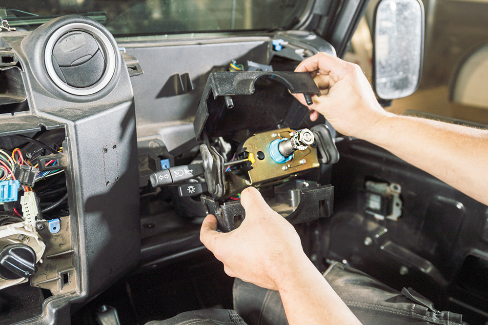
Column bracket: The stalk switches are removed by undoing the top clamp screw and withdrawing the stalk assembly off the column. The clamp is plastic, and prone to cracking: take care when handling it.

Connector block: The instrument cluster connector has a grey connector cover which needs removing. Ian uses a pick to push the retainer in, then withdraws the inner connector and loom.

Trim and proper: Ian trims the right-hand side off the metal stalk bracket to aid internal clearance once the cruise control stalk is fitted. This isn’t strictly necessary, but definitely helps with the process.

Make the hole: A hole is drilled on the right-hand side of the lower column cover for the cruise control stalk to fit to. Allow clearance for washer stalk operation.
Brake and throttle

Brake feed: For the brake circuit, Ian taps into the brake pedal switch. The plastic cover above the brake pedal simply pulls off, then the grey switch connector is unplugged.

Gaining access: To aid threading the loom behind the dash, remove the right-hand speaker and disconnect its feeds. We can now see through to the area above the pedal.

Throttle feed: The throttle loom piggybacks to the throttle connector. Above the pedal, the loom connector is disconnected and left ready. No wires to splice into, just plug it in.

Pro lesson: For neatness, the two brake loom wires are wrapped together using fleece loom tape. This is the tape for interior use, as it reduces potential dash noises.

Thread the needle: The brake loom is threaded in through the speaker aperture, through the dash mount bracket and down to the pedals. The ECU will eventually mount in this area.

Connect it up: The two loom wires need connecting to the brake switch wires. For this Ian makes a mid-point solder. First, he strips a section on each brake wire.

Strong joint: Each of the loom wires have their ends stripped, then each wire is wrapped around a corresponding brake switch wire. Mechanical joint is soldered for strength.

Brakes done: The joint is wrapped in electrical tape, then fleece loom tape. The brake pedal connector is reconnected, and the pedal cover replaced. The brake feed is finished.
Ignition and instrument connection

Ignition next: The feed for the ignition is led across the dash from the speaker aperture, under the steering column and out in the centre console. Now we’ll find a feed.

Radio supply: Ian prefers the radio connector for this, usually going for the white/orange wire on the radio loom connector block. Best practice is to confirm we have 12 volts.

Loom to ignition live: Another mid-point solder joint joins the loom to this. Again, it is wrapped in electrical tape, then with fleece loom tape. We’ve now got an ignition feed.

Instrument connector: We want a black/red wire here, but there are two. So, find pin 1 on the instrument connector block, and count across to a black/red wire.

Pin out, pin in: Ian pulls the wire’s pin out to aid access, then makes another mid-point solder joint on the speed pulse feed for the loom, and replaces the pin.
Clutch position feed

Clutch feed: The clutch feed will go off the clutch switch in the engine bay. Ian cuts the tip off an unused bulkhead grommet, and threads the red clutch feed through.

Clutch switch: Ian makes another mid-point solder joint into the black/white wire, wraps it in fabric tape, then reconnects the clutch switch. That’s all the wiring done.
Finishing off

Nearly done: The stalk is fitted to the column, then the stalk wiring pins are fitted to the connector. The wiring is all colour-coded, so is very simple.

Steering column: The column stalks go back on, taking care not to crack the plastic bracket. Refit the covers, and feed the wiring loom down through the lower dash.

Dash to finish: Reconnect and replace the instrument cluster and trim, reconnect and refit radio and centre console. Refit steering wheel, making sure it’s straight.

Connect and road test: Connect the stalk loom and the various ECU plugs. Turn on the ignition, and follow the calibration procedure via pedal presses, so the ECU learns each input.

Looking original: The new cruise control stalk fits neatly just below the wash/wipe stalk on the side of the column cowl, blending in as if it’s a standard fitment. Job done!
Like to have your own Land Rover library?
Try our Budget Digital Subscription. You'll get access to over 7 years of Land Rover Monthly – that’s more than 100 issues plus the latest digital issue. All issues are fully searchable so you can easily find what you are looking for and what’s more it’s less than 10p a day to subscribe. Click here to find out more details and start enjoying all the benefits now.